Introduction Since our premiere issue on March 1987, MSX-FAN has accumulated a total of 87 issues, including this one, for nearly nine years. Thanks for supporting us for such a long time. Our publication might had ended, but the MSX will remain with us forever. In commemoration, we decided to interview several key figures within the MSX industry to reminisce about the platform once more.
Kazuhiko Nishi: The Father of the MSX
The MSX computer platform started from an idea of a single person, ASCII Corporation president Mr. Kazuhiko Nishi. “I wanted a computer that anyone could use. A platform that any manufacturer could also use in the same matter as well.” And as one couldn’t imagined now, even with all the proud giants of the Japanese consumer electronics industry involved – Matsushita (Panasonic), Sony, Sanyo, Victor, Mitsubishi, Pioneer, Yamaha, Casio, Fujitsu, Toshiba, Hitachi, General, Canon – no matter who made it, an MSX was an MSX, giving the platform a universal face. Perhaps Mr. Nishi’s personality is what allowed that to happened. Therefore, we decided to interview Mr. Nishi for the first time in a while.
“The MSX is amazing because of the culture it created. And it’s made in Japan too. I think its users will be creating the Japan of tomorrow. It’ll be nice if they end up creating a unique world.” The MSX platform launched 12 years ago in 1983 and MSX-FAN followed suit four years later in 1987, lasting 9 years in publication. If a reader was in grade school when the magazine started, then he would be in college by now. “I’m already 40 years old. The people in charge of the manufacturers at the time have changed a lot and there are also people who joined ASCII because of their bond with the MSX.”
The first thing we asked him was the inside story of the MSX that he most wanted people to know. “The original MSX was born from the so-called 9918 video display processor from Texas Instruments. From there on, I’ve constructed the BASIC language of the Z80 processor which moves it. This was very different from what other computer companies were doing. The evolution at the time was to expand on BASIC. That’s exactly what NEC did with their PC-8001 series, the PC-8801 series, the PC-6001 series, ect. But I wasn’t thinking about extending the features of BASIC. I was thinking about adding graphics, sounds and controller functions to a computer. In other words, I wanted more interactivity from my computer.“
“After the MSX1 I wanted to make something even better, so we at ASCII created the 9938 video display processor with Yamaha. That’s how the MSX2 came to be.”
“After that, I was thinking there should be an operating system. Since the MSX uses an 8-bit processor, it had to be CP/M-80 compatible. As for the disk format, I thought it had to be MS-DOS compatible. Thus, we had a brilliant engineer called Suzuki within our company to create the MSX-DOS operating system. After we sold a million unit, we commission the construction of a dinosaur sculpture for an exhibition of sorts in the southern exit of Shinjuku Station. The reason why we put a dinosaur in the venue was because I wanted something that would attract children to computers and I thought it would be fun to recreate the image of a dinosaur with third-dimensional graphics.”
“Afterward, we’ve reworked the 9938 video processor into the 9958, which the MSX2+ ended using.”
“When thinking about the next thing, the first thing I thought about was how we would expand the video, CPU and DOS capabilities of the platform. The GDP (graphic display processor) once again came from Texas Instruments, but since we’ve already created our own VDP, we thought we could also create a faster CPU. So we decided to make a fast RISC processor. The results were quite surprisingly and I thought we created something really good. We licensed it back to Zilog, who made the Z80 processor, which is how we managed complete backwards compatibility”
“The R on the MSX turbo R stands for RISC. What I learned through the development of the MSX is that computers are rapidly converging development through the same architecture, making production of software much faster than before. If you can keep up with the speed you can make your complex software move much more smoothly. That’s why we’ve introduced a GUI (graphical user interface) this time. That was the MSX-VIEW.”
However, the turbo R ultimately became the last generation of the MSX produced.
“I wanted to continue development of the MSX after the last one by coming up with a CD-ROM attachment. I really wanted it to employ moving pictures (digital video and audio) capabilities to the hardware. I’ve assembled many people from Matsushita, Sony, NTT and Victor Japan who were acquainted with the MSX to form a research group. That group ended up becoming the Moving Picture Expert Group (MPEG), but during their research we ended up finding out that making movie playback work on the MSX was going to be extremely difficult.”
“After some careful thoughts, I considered fixing the architecture of the MSX turbo R by making it into a one chip set. But the research for this ended up being halted due to the discontinuation of the MSX. Thinking about it, the 8-bit address mode for the R800 processor was probably a bit too weak. Which is probably why there weren’t that many software (made for the turbo R).”
“I thought about what the Apple Inc. did as an example. First they made the Apple series of computers, then the Mac series and then they evolved their OS. With that in mind, the biggest advantage of the MSX, the fact that the software and hardware are unified, perhaps might had turned out to be its biggest disadvantage. The machine was easy to understand, but by not having the software as a separate component, it ended up dragging down the hardware specs completely. This time I want to make something that doesn’t rely on a specific CPU, but instead relies on software and sets the hardware specifications on a software level.“
He continued talking for three hours after this point and along the way he started coming with ideas for a new MSX specification at one point. He talked about wanting to form a new company called the MSX Corporation that would continue to produce and sell MSX computers. The merit of the MSX, its charm as a machine that is still loved after all this time, born from an ideaman as individualistic as Mr. Nishi, was felt strongly after the interview was over.
This article has been manually translated from English to other languages you can choose from, click here if you want to help with translations or suggest changes. 🇬🇧 – English 🇪🇸 – Español
The Nintendo 64 Released on 23/06/1996 in Japan, 29/09/1997 in America and 01/03/1997 in Europe
A quick introduction
Nintendo’s goal was to give players the best graphics possible, for this it will partner with one of the biggest players in computer graphics to produce the ultimate graphics chip.
The result was a nice-looking console for the family… and a 500-page manual for the developer.
Don’t worry, I promise you this article will not be that long… Enjoy!
CPU
The main processor is a NEC VR4300 that runs at 93.75 MHz, it’s a binary-compatible version of Silicon Graphics’ MIPS R4300i that features:
A MIPS III ISA: Succeeds the MIPS II featuring new 64-bit instructions. 64-bit words are called doublewords.
An internal 64-bit bus while connected to an external 32-bit data bus.
5-stage pipeline: Up to five instructions can be executed simultaneously (a detailed explanation can be found in a previous article).
24 KB L1 cache: Divided in 16 KB for instructions and 8 KB for data.
An internal 64-bit FPU is also included in this package, the CPU identifies it as a co-processor (COP1) although the unit is fitted next to the ALU and it’s only accessed through the ALU pipeline, meaning there’s no co-processing per se.
Simplified memory access
The way RAM is assembled follows the unified-memory architecture or ‘UMA’ where all available RAM is centralised in one place only and any component that requires RAM will access this shared location. The component arbitrating its access is, in this case, the GPU.
The reason for choosing this design comes to the fact that it saves a considerable amount of production costs while, on the other side, it increments access contention if not managed properly.
No DMA controller?
Due to the unified memory architecture, the CPU no longer has direct access to RAM, so the GPU will be providing DMA functionality as well.
RAM Available
Apart from the UMA, the structure of RAM is a little bit complicated, so I’ll try to keep it simple, here it goes…
The system physically contains 4.5 MB of RAM, however it’s connected using a 9-bit data bus where the 9th bit is reserved for the GPU (more details later). As a consequence, every component except the GPU will only find up to 4 MB.
The type of RAM fitted in the board is called Rambus DRAM or ‘RDRAM’ for short, this was just another design that competed against SDRAM on becoming the next standard. RDRAM is connected in serial (where transfers are done one bit at a time) while SDRAM uses a parallel connection (transfers multiple bits at a time).
RDRAM’s latency is directly proportional to the number of banks installed so in this case, with the amount of RAM this system has, the resulting latency is significant.
By contrast, the amount of available RAM on this console can be expanded by installing the Expansion Pak accessory: A fancy-looking small box that includes 4.5 MB. Curiously enough, the RAM bus must be terminated, so the console always shipped with a terminator (called Jumper Pak) fitted in the place of the Expansion Pak. Now, you may ask, what would happen if you switch on the console without any Pak installed? Literally nothing, you get a blank screen!
Graphics
The core of the graphics reside on a huge chip designed by Silicon Graphics called Reality Co-Processor running at 62.5 MHz. This package contains a lot of circuitry so don’t worry if you find it difficult to follow, the graphics sub-system has a very complex architecture! This design is based on the philosophy that the GPU is not meant to be a ‘simple’ rasteriser like the competitor’s. Instead, it should also be capable of accelerating geometry calculations (offloading the CPU), and for that, more circuitry will be needed.
Having said that, this chip is divided into three main modules, two of them are used for graphics processing:
Also known as RSP, it’s just another CPU package composed of:
The Scalar Unit: A MIPS R400-based CPU which implements a subset of the R400 instruction set.
The Vector Unit: A co-processor that performs vector operations with 32 128-bit registers. Each register is sliced in eight parts to operate eight 16-bit vectors at once (just like SIMD instructions on conventional CPUs).
The System Control: Another co-processor that provides DMA functionality and controls its neighbour module, the RDP (more about it later on).
In order to operate this module, the CPU stores in RAM a series of commands called Display list along with the data that will be manipulated, then the RSP reads the list and applies the required operations on it. The available features include geometry transformations (such as perspective projection), clipping and lighting.
This seems straightforward, but how does it perform these operations? Well, here’s the interesting part: Unlike its competitors (PS1 and Saturn), the geometry engine is not hard-wired. Instead, the RSP contains some memory (4 KB for instructions and 4 KB for data) to store microcode, a small program, with no more than 1000 instructions, that implements the graphics pipeline. In other words, it directs the Scalar Unit on how it should operate our graphics data. The microcode is fed by the CPU during runtime.
Nintendo provided different microcodes to choose from and, similarly to the SNES’ background modes, each one balances the resources differently.
The resulting frame must be sent to the Video Encoder in order to display it on screen (DMA and the Video Interface component are essential to accomplish this).
The theoretical maximum capabilities are 24-bit colour depth (16.8 million colours) and 640×480 resolution (or 720×576 in the PAL region). I mention it as ‘theoretical’ since using the maximum capabilities can be resource-hungry, so programmers will tend to use lower stats to free up enough resources for other services.
Quick demo
Let’s put all the previous explanations into perspective, for that I’ll borrow Nintendo’s Super Mario 64 to show, in a nutshell, how a frame is composed:
Primitive view of our scene In order to save polygons, some characters are modelled using sprites (quads)
To start with, our 3D models are located in the cartridge ROM, but in order to keep a steady bandwidth, we need to copy them to RAM first.
Then it’s time to build a scene using our models, the CPU could do it by itself but it may take ages, so the task is delegated to the RCP. The CPU will instead send orders to the RCP, this is done by carrying out these tasks:
Compose the Display List that contains the operations to be carried out by the RSP and store it in RAM.
Point the RSP where the display lists are.
Send microcode to the RSP to kickstart the Scalar Unit.
Afterwards, the RSP will start performing the first batch of tasks and the result will be sent to the RDP in the form of rasterisation commands.
Designs
Here are some examples of previous 2D characters for the Super Nintendo that have been redesigned for the new 3D era, they are interactive so I encourage you to check them out!
Tap to enable interactionKirby 64: The Crystal Shards (2000) 516 triangles
Modern visible surface determination
If you’ve read about the previous consoles, you came across the never-ending problem regarding visibility of surfaces and by now may think polygon sorting is the only way out of this. Well, for the first time in this series, the RDP features a hardware-based approach called Z-buffering. In a nutshell, the RDP allocates an extra buffer called Z-Buffer in memory. This has the same dimensions of a frame-buffer, but instead of storing RGB values, each entry contains the depth (Z-value) of the nearest pixel with respect to the camera.
After the RDP rasterises the vectors, the z-value of the new pixel is compared against the respective value in Z-buffer. If the new pixel contains a smaller z-value, it means the new pixel is positioned in front of the previous one, so it’s applied onto the frame-buffer and the z-buffer is also updated. Otherwise, the pixel is discarded.
Overall, this is a huge welcomed addition: Programmers do not need to worry anymore about implementing software-based polygon sorting methods which drain a lot of CPU resources. However, Z-buffer does not save you from feeding unnecessary geometry (discarded or overdrawn, both consuming resources). For this, game engines may choose to include an occlusion culling algorithm to discard unseen geometry as early as possible.
Secrets and limitations
SGI clearly invested a lot of technology into this system. Nonetheless, this was a console meant for the household and as such, it had to keep its cost down. Some hard decisions resulted in difficult challenges for programmers:
Due to the huge number of components and operations in the graphics pipeline, the RCP ended up being very susceptible to stalls: An undesirable situation where sub-components keep idling for considerable periods because the required data is delayed at the back of the pipeline.
This will always result in performance degradation and is up to the programmer to avoid them. Although to make things easier, some CPUs such as the Scalar Unit implement a feature called Bypassing which enables to execute similar instructions at a faster rate by bypassing some execution stages that can be skipped. For example, if we have to compute sequential ADD instructions there’s no need to write the result back to a register and then read it back every time each ADD is finished, we can instead keep using the same register for all additions and do the write-back once the last ADD is completed.
The universal video out
Nintendo carried on using the ‘universal’ Multi Out port found on its predecessor, bad news is that it no longer carries the RGB signal! It looks to me like another measure to save costs, since RGB wasn’t used anyway in the previous console.
Good news is that the three lines can still be reconstructed in the first revisions by soldering some cables and fitting an inexpensive signal amplifier. This is because the video digital-to-analogue converter transmit an RGB signal to the video encoder. However, latter units combined both chips, so the only remaining option is to bypass the video DAC and encoder altogether with a custom one that exposes those signals.
Audio
Before we go into the details, let’s define the two endpoints of the audio sub-system:
Our starting point is the cartridge ROM, it contains data that only the CPU can interpret.
The ending point is the Digital-to-Analog converter or ‘DAC’, which only understands waveform data.
Now, how do we connect both ends? Consoles normally include a dedicated audio chip that does the work for us. Unfortunately, the Nintendo 64 doesn’t have such dedicated chip, so this task is distributed across these components:
The main CPU: Transfers the audio data from the game’s ROM to RAM, then it initialises Audio Lists to be used by the RSP.
The RSP: With the use of even more microcode, it interprets the audio lists previously stored in RAM and performs the required operations to the audio data which, for example, can include:
Uncompressing ADPCM samples and applying effects.
Sequencing and mixing MIDI data using audio banks stored in RAM as well.
The resulting data is, as expected, waveform data. This is then sent to the Audio Interface or ‘AI’ block which will then transfer it to the digital-to-analogue converter. The resulting waveform contains two channels (since our system is stereo) with 16-bit resolution each.Overview of how the audio pipeline is often programmed
The repertoire
Time to checkout the soundtracks made for the N64. There are too many (good ones) to mention in this article, so here are some that caught my attention:The Legend of Zelda: Majora’s Mask (2000) The music of this game is tied to its daunted atmosphereBomberman Hero (1998) This game has nice and unique house-based soundtrack
Secrets and limitations
Because of this design, the constraints will depend on the implementation:
Sampling rate can be up to 44.1Hz, but using the top rate will steal lots of CPU cycles.
There’s no strict limit in the number of channels, it all depends how much the RSP is capable of mixing (often around 16-24 channels if processing ADPCM or ~100 if PCM).
Memory is another concern, while competitors relied on larger mediums (i.e. CD-ROM) and dedicated audio memory, Nintendo 64 cartridges hold much less data (let alone music data) and have to share its main memory with other components. For those reasons, players may notice that N64 ports contain lesser quality music or repeated scores.
A method for overcoming this limitation consisted in implementing a software sequencer that could ‘construct’ the samples at runtime using a pre-populated set of sounds (similar to MIDI music).
Operating System
Similar to the PS1 and Saturn, N64 games are written for bare-metal. However, there are no BIOS routines available to simplify some operations. As a substitute, games embed small OS that provides a fair amount of abstraction to efficiently handle the CPU, GPU and I/O.
This is not the conventional desktop OS that we may imagine at first, it’s just a micro-kernel with the smallest footprint possible that provides the following functionality:
Multi-Threading (bear in mind the CPU is single-core).
Scheduling and Preemption.
Simplified register and I/O access.
The kernel is automatically embedded by using Nintendo’s libraries. Additionally, if programmers decide not to include one of the libraries, the respective portion of the kernel is stripped to avoid cartridge space being wasted.
Input/Output
As you know by now, I/O is not directly connected to the CPU, so the RCP’s third module (which I haven’t mentioned until now) serves as an I/O interface, it basically communicates with the CPU, controllers, game cartridge and Audio/Video DACs.
Games
Nintendo held on to the cartridge medium for storage and as a consequence, games enjoyed higher bandwidths (between 5-50 MB/s depending on the ROM’s speed) while being more expensive to produce. The biggest cartridge found in the market has 64 MB.
Inside cartridges manufacturers may include extra memory (in the form of EEPROM, flash or SRAM with a battery) to hold saves, however this is not a strong requirement any more since certain accessories could be used to store saves as well.
Accessories
The Nintendo 64 controller included a connector used to plug in accessories, some of them are:
The Controller Pak: Another medium (similar to Sony’s Memory Card) used to store save data and use it on other consoles.
The Rumble Pak: Contains a small motor in order to provide haptic feedback, useful for immersing the player on certain games.
All accessories connected to the controller are managed by the Peripheral Interface.
Apart from that, this console included a special connector at the bottom of its motherboard which was meant to be used by the yet-unreleased Disk drive, some sort of an ‘extra floor’ that contained a proprietary disk reader, the drive was only released on Japan nonetheless and eventually cancelled for the rest of the world.
Source Development Kit
In general, development was mainly done in C, assembly was also used to achieve better performance. While this system contained a 64-bit instruction set, 64-bit instructions were rarely used since in practice, 32-bit instructions happened to be faster to execute and required half the storage.
Libraries contained several layers of abstractions in order to command the RCP, for example, structs like the Graphics Binary Interface or ‘GBI’ were designed to assemble the necessary Display lists more easily, the same applied for audio functions (its struct was called Audio Binary Interface or ‘ABI’).
In terms of microcode development, Nintendo already provided a set of microcode programs to choose from, however if developers wanted to customise it, that would indeed be a challenging tasks: The Scalar Unit instruction set wasn’t initially documented (at the request of Nintendo, of course), later on the company changed its position and SGI finally released some documentation for microcode programming.
Hardware used for development included workstations supplied by SGI, like the Indy machine which came with an extra daughterboard called U64 that contains the hardware and I/O of the retail console. Tools were supplied for Windows computers as well.
Other third-party tools consisted in cartridges featuring a long ribbon cable that connected to the workstation. This cartridge fitted in a retail Nintendo 64 but included internal circuitry to redirect the read requests from the console to the workstation’s RAM. The deployment/debugging process was carried out by transferring a copy of the game to RAM and then, when the console was switched on, it would start reading from there.
Anti-piracy / Region Lock
The anti-piracy system is a continuation of the SNES’ CIC. As you know, bootleg detection and region locking are possible thanks to the CIC chip (which must be present in every authorised game cartridge), the Nintendo 64 improved this system by requiring different games to have a specific variant of the CIC chips in order to make sure the cartridge was not a counterfeit or contained a CIC clone, the Peripheral Interface or ‘PIF’ would do checksum checks at the start and during gameplay to supervise current CIC installed on the cartridge.
If by any reason the PIF considers the current cartridge is not valid, it will then induce the console in a permanent freeze.
Region-locking was done by slightly altering the shape of the cartridge between different regions so the user can’t physically insert the game on an N64 from a different region.
Overall, there was not too much concern regarding piracy thanks to the use of cartridge medium, although game prices were three times higher than CD-based ones.
Unused ports
As silly as it may seem, Nintendo left one door opened: The Disk Drive port.
A few companies reversed engineered the interface in order to develop their own hardware, and some of the resulting products became a concern for piracy.
I guess the one worth mentioning is the Doctor v64, this device has the same shape as the Disk Drive but included a CD-ROM drive that’s used to clone the contents of the cartridge to a CD, the opposite (reading Roms from a CD) is also possible.
Emulation
When I was a kid I used to play some N64 games on a Pentium II machine using an emulator, it wasn’t that bad but then I wondered now how the freck was it able to happily emulate a complex 64-bit machine since, among other things, my PC barely had enough RAM to keep the integrated video alive.
The truth is, while reproducing the architecture of this console can be complex, things like microcode will give a hint of what the console is trying to do, and since emulators don’t have to be cycle-accurate, they can apply enough optimisations to provide more performance in exchange for real emulation. Another example are the 64-bit instructions, since games barely used them, emulation speed would hardly be hit when running on a 32-bit host machine.
That’s all folks
I have to say, this article may be the longest one I’ve ever written, but hopefully you found it a nice read!
I’ll probably take the following days to tide up some things on the website instead of starting to write the next article.
Anyway, if you enjoy my articles and would like to help, please take a look here. If you have any comments or suggestions, feel free to email me here.
This article is part of the Architecture of Consoles series. If you found it interesting please consider donating, your contribution will be used to get more tools and resources that will help to improve the quality of current articles and upcoming ones.
A list of desirable tools and latest acquisitions for this article are tracked in here:
## Interesting hardware to get (ordered by priority)

- Nintendo 64 console and a controller (£40 - £60)
- A N64 game (£5 - £15)
- Any Dev kit (only if found at a reasonable price)
- N64 DD (only if found at a reasonable price)
## 2020-09-23

- Added info about video out

## 2020-05-20

- Avoid mixing up TMEM with actual Texture cache. Thanks monocasa from Hackernews

## 2020-05-08

- Added Mario 64 screenshot with original resolution

## 2020-04-22

- Improved 9-bit explanation. Thanks /u/mallardtheduck

## 2020-04-14

- Small changes to perspective correction info

## 2020-04-11

- Dedicated more text to the visibility approach

## 2020-02-26

- Expanded texture unit section.

## 2020-01-11

- Added repertoire

## 2019-10-29

- Added some 3d models to fiddle with

## 2019-09-17

- Added a quick introduction
- Corrected some explanations

## 2019-09-12

- Released to the public, yay
The original Playstation. Released on 03/12/1994 in Japan, 09/09/1995 in North America, 29/09/1995 in Europe
A quick introduction
Sony knew that 3D hardware can get very messy to develop for, for this reason, their new console will keep its design simple and practical… Although this may come with a cost!
CPU
The main processor is a modification of LSI’s CoreWare CW33300 which, at the same time, is binary-compatible with SGI’s MIPS R3051. This chip runs at 33.87 MHz and it features:
The MIPS I ISA: A 32-bit RISC instruction set, it includes multiplication and division instructions.
One ALU and one shifter.
5-stage pipeline: Up to five instructions can be executed simultaneously (a detailed explanation can be found in a previous article).
4 KB instruction cache and 1 KB of data cache (the original CoreWare CW33300 contained 2 KB of data cache): The data cache is actually Scratchpad RAM, meaning that it can have other uses apart from behaving as L1 cache.
Like other MIPS R3000-based CPUs, it supported configurations with up to four coprocessors, Sony customised it with two:
System Control Coprocessor or ‘COP0’: A MMU that provides virtual memory by using a Translation Lookaside Buffer or ‘TLB’. Not all the features that come with virtual memory are available though, for example, memory protection is disabled since games are programmed for bare-metal (without running from an OS). On the other hand, this MMU still gives interrupt support, exception handling and breakpoints, these are used for debugging.
Geometry Transformation Engine or ‘GTE’: A special math processor used for vector and matrix calculations. While only containing a fixed-point unit, it still provides useful operations for 3D graphics such as lighting and polygon transformations.
Additionally, there’s an extra processor found in the main CPU:
Motion Decoder or ‘MDEC’: Provides full motion video playback (known as ‘FMV’) and transfers the decoded frames to the GPU using DMA.
Taking over the CPU
Sometimes any subsystem (graphics, audio or CD) may require large chunks of data at a fast rate, however the CPU may not be able to always keep up with the demand.
For this reason, the CD-ROM Controller, MDEC, GPU, SPU and the Parallel port have access to an exclusive DMA controller that takes control of the main bus whenever they require it.
Graphics
A large part of the graphics pipeline is carried out by the GTE. This includes perspective transformation, which projects the 3D space onto a 2D plane using the camera’s perspective. The processed data is then sent to Sony’s proprietary GPU for rendering.
Drawing the scene
If you’ve been reading the Sega Saturn article, let me tell you that the design of this GPU a lot simpler!
Insomniac’s Spyro: Year of the Dragon will be used as example to show how a scene is drawn.
To start with, the GPU uses triangles as primitives to form 3D models. Being the only available primitive means that backgrounds and foregrounds make no difference in terms of composition (both are made of triangles). 2D games inherit the same nature: They are just flat polygons (two triangles joined to form a quadrangle). The GPU also includes routines for handling quadrangles as sprites.
The CPU sends geometry data to the GPU by filling its internal 64 byte FIFO buffer with commands (up to three). Basically, a command states how and where to draw one primitive. Once the geometry is received, clipping is applied to skip operations over unseen polygons (residing outside the camera’s viewport).
Compared to the more complex Sega Saturn, the GPU only requires a single frame-buffer.
Designs
Here are some examples of game characters designed from the ground up for the 3D era, they are interactive so I encourage you to check them out!
Tap to enable interactionCrash Bandicoot (1996) 732 triangles
Playing with VRAM
The system features 1 MB of VRAM that will be used to store the frame-buffer, textures and other resources the GPU will need to access almost instantly. In theory, with the available amount of VRAM one could allocate a massive frame-buffer of 1024×512 pixels with 16-bit colours or a realistic one of 960×512 pixels with 24-bit colours allowing to draw the best frames any game has ever shown… This sounds pretty impressive right? Well, it does raise a couple of issues, for instance:
Those dimensions will have to be rescaled to follow a standardised definition so the video encoder can broadcast it to conventional TVs.
How is the GPU going to be able to draw anything in time if there is no space left for the rest of materials (i.e.textures, colour tables, etc)?
The PS1’s GPU can only draw frame-buffers with up to 640×480 pixels and 16bpp colours.
Alright, so let’s have a 16 bpp 640×480 buffer instead, which leaves 424 KB of VRAM for materials. So far so good? Again, such resolution may be fine on CRT monitors, but not really noticeable on those 90s TVs everyone had at their homes. Then, is there any way to optimise the frame-buffer? Introducing adjustable frame-buffers.
In essence, instead of wasting valuable VRAM by using ‘unappreciated’ resolutions, this console’s GPU allows to decrease the dimensions of the frame-buffer to effectively increment the space available for other resources. A common setup consisted in dividing the 640×480 frame-buffer into two 320×480 ones, then using a technique called page-flipping to render multiple scenes at the same time. Page-flipping consists in switching the location of the frame for display between the two available whenever the game wants it, allowing the game to render one scene while displaying another, thus hiding any flickering effect and improving loading times (something that the player will certainly appreciate!).
Overall, our suggested layout only consumes 600 KB of VRAM. The rest (424 KB) was often used to store colour lookup-tables and textures that, combined with 2 KB of texture cache available, results in a very convenient and efficient setup.
Finally, it is worth mentioning that VRAM can be mapped using multiple colour depths simultaneously, meaning that we could allocate a 16 bpp frame-buffer next to 24 bpp bitmaps (e.g. FMV frames). This is another feature facilitating further optimisation of space.
Secrets and Limitations
Whereas the PS1 had a very simple and suitable architecture, problems ended up arising anyway. Surprisingly, certain issues were tackled with very clever workarounds!
Textures jiggle a bit while they move Square Soft’s Final Fantasy VIII (1999)
The routines used for handling geometry and applying textures were known to carry some inaccuracies:
GPU coordinates are limited to fixed-point units: That means no decimals (thus no precision), contributing to sudden jumps when polygons move slightly.
As you know, affine transformations have no sense of depth, which may confuse the user’s perception when the camera is close to the model and is positioned perpendicular to the viewer.
Finally, the smallest size of a polygon in this system is a pixel, making small polygons (no matter how small) to be rendered as a single pixel. Now, this means that textured polygons may lose part of their texture if their size becomes smaller than a pixel. Furthermore, complex models may suffer from edges constantly shaking.
This effect is more apparent when using a small frame-buffer or rendering models at a distance. Modern systems tackled this by implementing sub-pixel resolution methods, which handles polygons using fractions of pixels.
These explain why users may notice instabilities while playing some games. The effect is also referred as texture warping, some games often resorted to tessellation (dividing a big polygon into smaller ones) in order to reduce these unwanted effects, others just reduced the amount of textures in favour of solid colours.
Audio
The Sound Processing Unit or ‘SPU’ takes care of this. It supports the enormous amount of 24 channels of 16-bit ADPCM samples (a more efficient version of the well-known PCM sampling) with a sampling rate of 44.1 KHz (Audio CD quality).
This chip also provides the following capabilities:
Pitch modulation: As the name suggests, games can automatically alter the pitch of their samples instead of needing to store extra ones. Useful for music sequencing.
ADSR Envelope: These are a set of properties available for sound modulation.
Looping: This allows to instruct the system to play a piece of audio repeatedly.
Digital reverb: Simulates the sample being played inside an specific atmosphere in order immerse the player.
512 KB of SRAM are provided as audio buffer. This memory is accessible from the CPU and CD controller. Games only have 508 KB available to store samples, the rest is reserved by the SPU to process Audio CD music. This amount is reduced even further if reverb is activated.
Games
Similarly to the Saturn’s boot process, after turning this console on, it will:
Execute a small OS found in the BIOS ROM.
Initialise the hardware.
Display the splash screen.
If there is a CD inserted, the CD-ROM controller will check if it’s genuine:
It is: The controller will allow to read its content.
The CPU will look for ‘SYSTEM.CNF’ and continue execution from there.
It’s not: The CPU will display an error message.
With no CD inserted, the CPU will open the memory card manager, the user is now in control.
Inside the manager there’s an option to open the CD audio player.
Games have all the facilities that the CD medium provides: Large storage (640 MB), good audio quality and a ‘not-so-slow’ read speed thanks to the 2x drive. Additionally, there are two I/O ports (Serial and Parallel) available for add-ons. However, these were removed in later revisions of the console due to lack of adoption and the fact that they could potentially be used to crack the copy protection system.
The SDK provided C libraries which used BIOS routines to access the hardware. This is the main factor that helped to emulate the PS1 on a wide range of platforms.
Along with the SDK, Sony also distributed specialised hardware like the DTL-H2000, a dual-slot ISA card containing the internals and I/O of the PS1, plus extra circuitry for debugging purposes. The board has access to the host’s hard drive and can execute PS1 software without restrictions. Software and drivers used to communicate with the card ran on PCs with Windows 3.1 or 95.
I/O design
The port of the controller and the Memory Card are electrically identical so the address of each one is hardcoded, Sony altered the physical shape of the ports to avoid accidents.
Communication with these devices is accomplished using a serial interface. Commands sent from the console will be delivered to one of the two slots (either ‘mem. card 0’ and ‘controller 0’, or ‘mem. card 1’ and ‘controller 1’). Then, both accessories will answer with their unique identifiers, this will allow the console to focus on a particular type of device (memory card or controller) from now on.
Anti-piracy / Region Lock
Like any other optical media, in order to fetch data from a CD, a laser beam is used to read the pits (zeroes) and lands (ones) from the track of the disc. Now, conventional discs are not 100% flat and they often have tiny fluctuations in their tracks. These defects are completely unnoticeable while reading the data since lasers can automatically calibrate themselves as they read.
This is what Sony based their copy protection on: The CD reader of the PS1 will only accept discs whose specific region (sector 4) is engraved using a defined frequency informally known as Wobble Groove, which is only applied during mastering and cannot be replicated through conventional burners. This sector in particular will contain one of the following set of characters (each representing a different piece of information):
SCEA → Sony Computer Entertainment of America.
SCEE → Sony Computer Entertainment of Europe.
SCEI → Sony Computer Entertainment of Japan.
As you can imagine, the reader applies region-locking using this technique as well.
On the other side, this check is only executed once at the start, so manually swapping the disc just after passing the check can defeat this protection… with the risk of damaging the drive. In any case, later games took matters into their own hands and often reinitialised the drive in-game so the check would be executed again, in an effort to prevent users from performing this trick.
Alternatively, tiny boards programmed to mock the wobble signal could be soldered in the console. These boards are known as Modchips and, while legally questionable, were incredibly popular.
The use of emulators were seen as a threat for publishers as well. As a result, some games included their own checks (mostly checksums) to combat any type of unauthorised use or modification. One of the checks I was told consisted in deliberately reinitialising the drive and then making it read specific sectors that would not pass the wobble groove check. If this managed to unlock the drive anyway, the game (still residing in RAM) would happily reveal its anti-piracy material. Notice that this approach can also affect modded consoles using genuine games.
This article is part of the Architecture of Consoles series. If you found it interesting please consider donating, your contribution will be used to get more tools and resources that will help to improve the quality of current articles and upcoming ones.
A list of desirable tools and latest acquisitions for this article are tracked in here:
## Interesting hardware to get (ordered by priority)

- First PS1 revision with a controller (£5 - £20 ?)
- Any game (£5 ?)
The Sega Saturn, released on 11/05/1995 in America and 08/07/1995 in Europe
A quick introduction
Welcome to the 3D era! Well… sorta. Sega enjoyed quite a success with the Megadrive so there’s no reason to force developers to write 3D games right now.
Just in case developers want 3D, Sega adapted some bits of the hardware to enable polygon drawing as well, hopefully, the result didn’t get out of hand!
CPU
The system has not one, but two Hitachi SH-2 CPUs running at ~28.63MHz each. While both physically identical, they are placed in a master-slave state, where the first one may send commands to the second one. This can achieve some degree of parallelism, albeit both sharing the same external bus (which can lead to congestion).
These processors are part of the Hitachi SH7600 Series, a series designed for embedded systems featuring:
SuperH ISA: A special 32-bit RISC instruction set where instructions are 16-bit long. Not only this design reduces the size of the program, but since the CPU fetches instructions in 32-bit batches, two instructions can be retrieved in one cycle.
Five-stage pipeline: Execution of instructions is divided into five steps or stages. The CPU will queue up to five instructions where each one is allocated in one stage. This allows to take advantage of all the CPU’s resources without idling while also incrementing the number of instructions executed per unit of time.
One multiplication unit: Speeds up multiplication operations with 64-bit/32-bit integers.
Two 32-bit internal buses: giving a theoretical 64-bit bus, registers are still 32-bit.
32-bit external bus shared across the two CPUs.
4 KB cache: Stores a small amount instructions and data previously fetched from memory to speed up future reads.
The specific CPU model selected for this console, the ‘SH7604’ or just ‘SH-2’, contain the following additions:
One division unit: Speeds up division operations with 64-bit/32-bit integers.
Internal DMA controller: Transfers data from memory independently (without the need of using the CPU).
Having two CPUs doesn’t mean that games will work twice as fast, in practice, this requires very complex programming to efficiently manage CPUs that share the same bus! Here is when cache comes very handy.
The console contains an additional coprocessor, the Saturn Control Unit or ‘SCU’ which is composed of two modules:
A DMA controller: Arbitrates access to WRAM across the three main buses without the intervention of the CPUs.
A DSP: Used as a fixed-point Geometry unit. Compared to the SH-2, it does matrix/vectors calculations such as 3D transformations and lighting faster, however, it runs at half-speed and has a more complex instruction set, it also relies on the SH-2’s WRAM to fetch and store data (using the DMA).
A divided choice of memory
The system contains a total of 2 MB of RAM for general purpose usage, this is called Work RAM or ‘WRAM’. Now, these two megs are split between two very different blocks. The first one provides 1 MB of SDRAM and due to its fast access rates, this block is also called ‘WRAM-H’. The other block contains the other megabyte, but it’s named ‘WRAM-L’ since it uses DRAM instead, resulting in lower rates. It’s worth mentioning that the SCU can’t access the latter type.
Graphics
Since the Saturn is the first ‘3D console’ reviewed for this series, let us first go over the fundamental design changes that made way to the new generation of 3D graphics:
GPU now relies on a frame-buffer: Graphics are no longer required to be rendered on-the-fly, instead the GPU reserves a portion of VRAM to draw a bitmap with all the computed geometry requested by the CPU, then a video encoder picks up that region and outputs it through the video signal.
Consequently, having this reserved ‘working space’ allows the GPU to continue manipulating the bitmap even after finishing rendering the scene, so the CPU may now offload some exhaustive tasks such as lighting and anti-aliasing to the GPU. Here is when the term of graphics pipeline starts to gain momentum.
More VRAM required: The use of a frame-buffer implies an increment of memory requirements (which is not a big issue any more), the amount of RAM required for a frame-buffer is proportional to the dimension of the screen and the number of colours used. As an example, with 600 KB of VRAM we can contain a frame-buffer of 640×480 pixels wide with 32k colours per pixel (16 bpp).
Additionally, programmers are free to organise their VRAM usage: Not every single bit has to be allocated for the frame-buffer, so why don’t we also use it to cache textures, render other frame-buffers concurrently and add colour lookup tables to speed things up?
CPU incorporates vector operations: A GPU with 3D capabilities would be incomplete without a proper CPU capable of feeding the required geometry. For that reason next-gen CPUs include a form of specialised instructions that accelerates vector calculations, these are known as Single instruction multiple data or ‘SIMD’ extension.
In the case of the Saturn, vector operations are accelerated by the Saturn Control Unit (not by the CPUs).
Sega’s offering
This console includes two 32-bit proprietary GPUs, each one serving different purposes while working concurrently:
The Video Display Processor 1 or ‘VDP1’ is a custom chip specialised in rendering polygons, it is designed to use quadrilaterals as primitives which means that it can only compose models using 4-vertex polygons.
Textures are applied using the following algorithms:
Forward Texture Mapping to map the textures into each quad. It is subject to some aliasing.
Bilinear Approximations to correct unstable textures (noticeable while slowly moving the camera view), this effect is also called texture warping.
Since texture-related operations tend to make intensive use of the memory bus, programmers are provided with 512 KB of VRAM to cache textures and avoid congesting the bus, resulting in better fill-rates.
The chip also provides this selection of effects:
Two shading algorithms (Flat and Gouraud) for lighting.
Edge anti-aliasing to smooth out jagged edges.
Clipping to discard polygons outside the camera’s viewport.
Transparency.
Two 256 KB frame-buffers are available to concurrently draw new scenes of the game without breaking the current one being displayed (double-buffering). When the secondary buffer is finished being drawn, it is then copied to the primary one during special events (like V-Blank) so the user doesn’t notice this operation.
Defining the problem
As you can see the architecture of the graphics sub-system is quite complex, so it’s interpreted differently depending on the needs:
As a powerful 2D console
The capabilities of the Saturn for drawing 2D scenes were huge compared to the MegaDrive or SNES, although they weren’t the main selling point of this console.
In this case, the VDP1 is tasked to draw plain individual quadrilaterals that are filled with textures (one per polygon), this is how sprites are achieved.
As a challenging 3D console
Here’s where the Saturn shined and struggled at the same time. While this console had eight processors to take advantage of, it all came down to:
Whether programmers would be able to master most of the console’s features during a small time frame (remember the console’s commercial lifespan would be over once its successor is released, or even announced).
Whether their game would be shipped at a reasonable date.
For this reason, most games ended up dramatically ranging in quality since each studio came up with their unique solution, the possible permutations were almost infinite!
3D models of characters without textures or background Notice the primitives used to build the models Virtua Fighter Remix (1995)
So far we’ve been using single quadrilaterals to form sprites or background layers. But what if we group multiple primitives to form a more complex figure? This is how 3D models come to fruition.
In a nutshell, the CPU is tasked with formulating a 3D world, while both VDPs will be commanded to project it, apply textures and effects on it and finally display it in a 2D space.
An introduction to the visibility problem
When 3D polygons are projected onto a 2D space, it is crucial to determine which polygons are visible from the camera’s position and which are hidden behind. Otherwise, models are not drawn correctly, effects like transparency appear ‘broken’ and ultimately, hardware resources are wasted. This process is widely known as Visible surface determination or ‘VSD’ and it’s a fundamental problem in the world of computer graphics. There are multiple papers published that describe algorithms that tackle this at different stages of the graphics pipeline. Some of them give very accurate results, while others trade precision for better performance. Now, unlike academic/professional equipment, consumer hardware is incredibly limited, so the choice of algorithm is narrowed down to just a few… or none whatsoever.This engine ditched Z-sort in favour of a binary space partitioning (BSP) approach, fixing the glitches Project Z-Treme (2019, Homebrew)
The Sega Saturn approach is what I consider a ‘semi-solved’ case. The VDP1 doesn’t implement any VSD function: You either feed the geometry in the correct order or you get a mess. However, Sega provided a graphics library called ‘SGL’ that implemented a solution called Z-sort or Painter’s algorithm which performs polygon sorting by software.
Essentially, SGL allocates a buffer to sort the polygons based on the distance from the camera (from furthest to nearest), then, it issues the display commands to the VDP1 in that order. One of the issues of Z-sort with 3D spaces is that its distance value (Z-order) is approximated, so graphic glitches may still appear. For this, programmers can skip SGL in favour of implementing their own algorithm.
In later articles, you will see alternative approaches. Some still rely on software, while others are accelerated by hardware.
The new designs
These are some examples of characters that were re-designed for this console, the models are interactive so do try to fiddle with them!
Tap to enable interactionTails in Sonic R (1997) 425 triangles
The transparency issue
The Sega Saturn is capable of drawing half-transparent graphics, in other words, mixing overlapping layers of colours to give the illusion we can see through them. Unfortunately, both VDPs aren’t as coordinated as one would expect, so this effect will not work properly when these layers are spread around the two VDPs at the same time.
As a workaround, games could activate the ‘mesh’ property on a texture. With ‘meshed’ textures, the VDP sets the odd X/Y texture coordinates as ‘transparent’. Making it possible to blend other layers using the transparent pixels. Curiously enough, the mesh would appear blurred if the console was connected to the TV using the composite video signal (which was pretty much the standard back then, aside from RF) resulting in an accidental but effective way to accomplish halt-transparency.
As you may suspect, this just wasn’t viable for some games, so at the end, these had no option but to ditch half-transparency all-together. Although… some found ingenious fixes, take a look at these two cases:Sega’s Daytona (1993)Traveller’s Tales’ Sonic R (1997)Both games command the VDP1 to draw foreground objects and background scenery. The VDP2 draws instead the landscape image far away and the stats in front of the 3D models. With this layout, VP1 models with half-transparency won’t refract the VDP2’s landscape as the VDP1 is not aware of the VDP2’s frame-buffers.
Apart from my terrible gameplay, you’ll notice that the background of the first game pops out of nowhere (no half-transparency) whereas the second game not only accomplished half-transparency but also a fading effect: Traveller’s Tales found a workaround by changing the ‘mix ratio’ registers of the VDP2 (used for defining the texture’s alpha) combined with switching the lighting levels as the character gets closer.
Audio
The sound subsystem consists in several components:
Motorola 68EC000: Works as a controller and interfaces with the main CPUs.
Saturn Custom Sound Processor: Composed of two modules:
A multi-function sound generator: Supports up to 32 channels for PCM samples with a sampling rate of 44.1 kHz (CD quality), or 8 channels for FM synthesis (the remaining 24 channels are used as operators).
A DSP: Applies effects like reverb or room acoustics.
512 KB of RAM: Used to store sound programs or samples.
Games
The console starts by booting from the IPL (initial program loading) ROM which initialises the hardware and displays the splash screen. Then the game is loaded from the 2x CD-ROM reader, its medium (CD) has a capacity of 680 MB of data.
Development
At first, Sega didn’t provide complete software libraries and development tools (even the documentation was inaccurate) so the only way to achieve good performance was through harsh assembly. Later on, Sega released complete SDKs, hardware kits and some libraries to ease I/O and graphics operations. Overall, games are written in a mix of C and various assemblies targeting individual components.
I/O
Peripherals are handled by the SMPC (System Management & Peripheral Control), a micro-controller that also provides a real-time clock and allows the SH-2 to program them.
Expansion
The cartridge slot is used to provide storage (save data) or extra RAM. Another expansion slot is found near the CD Reader, this one expects a ‘Video CD Card’ that, as the name suggests, enables to play Video CD.
Anti-Piracy & Homebrew
Copy protection on CDs is applied by burning special data out of reach from conventional burners, the Saturn CD reader refuses to read the disc if the out-of-reach data is not found. The disc reader also contains a custom SH-1 processor that interfaces with the rest of the system using encrypted communication. It’s worth mentioning that Saturn CDs don’t have any reading protection, so you can actually access its content from a PC.
A popular method of disabling the copy protection was by installing mod-chips that could trick the CD reader when a burned disc is inserted.
A more sophisticated method for running unauthorised code was published in 2016 (almost 20 years later) by exploiting the fact that the Video CD add-on can inject unencrypted code to the CD subsystem (bypassing the CD reader altogether), this finally allowed load custom code without depending on the ageing drive.
This article is part of the Architecture of Consoles series. If you found it interesting please consider donating, your contribution will be used to get more tools and resources that will help to improve the quality of current articles and upcoming ones.
A list of desirable tools and latest acquisitions for this article are tracked in here:
## Interesting hardware to get (ordered by priority)

- A PAL/NTSC/JAP Saturn console with a controller (£50 - ?)
- An optical drive emulator (only if found at a reasonable price)
## 2020-04-10

- New sub-section explaining the visibility problem

## 2020-04-08

- New memory section, thanks /u/EmeraldNovaGames.
- Added more content to the CPU section, thanks Ponut64 from Sega Xtreme.

## 2020-04-07

- Small corrections, thanks /r/SegaSaturn.

## 2020-02-18

- Improved some explanations.

## 2019-10-30

- Added 3d models.

## 2019-09-17

- Better wording.

## 2019-09-17

- Added a quick introduction.

## 2019-08-27

- Corrected some explanations.

## 2019-08-09

- Improved wording.

## 2019-08-03

- Ready for publication.
The Super Nintendo or Super Famicom in Japan Released on 21/11/1990 in Japan and 11/04/1992 in Europe
A quick introduction
Nintendo managed to bring the next generation of graphics and sounds without using expensive off-the-shelf components. Consequently, the Super Nintendo was designed with expandability in mind: In a world where CPUs are evolving faster than the speed of light, Nintendo depended on game cartridges to make its console shine.
CPU
The main processor is a Ricoh 5A22. It’s based on the Western 65C816, a 16-bit upgrade of the classic MOS Technology 6502. Since the SNES shares the same foundation of the NES’ CPU, there’s a slight possibility that the SNES was originally planned to be compatible with NES games.
The CPU employs a variable clock speed that will reach up to 3.58 MHz during register operations and down to 1.79 MHz when accessing slow external buses (i.e. the serial/controller port).
The 5A22 features:
A 65816 ISA: A 16-bit instruction set which extends the original 6502 ISA, but doesn’t implement the undocumented instructions some NES games ended up using.
The accumulator (where arithmetic operations are performed) and index register (used to compute memory addresses) can switch between 16-bit and 8-bit mode.
New 16-bit multiplication and division units added by Ricoh, which provide the CPU with the ability to carry out these type of operations by hardware (the 65C816 doesn’t include any dedicated instructions for multiplication or division).
8-bits external data bus: Meaning that it takes twice the cycles to move its registers across external memory!
Ricoh’s additions
Apart from the extra registers, Ricoh customised the core design to include two exclusive DMAs (Direct Memory Access) that enables to move memory around without the intervention of the CPU (resulting in faster speeds).
For this design to work, regions of memory are referenced using two different address buses:
24-bit ‘A Bus’ controlled by the CPU: Connects the cartridge, CPU and WRAM.
8-bit ‘B Bus’ controlled by the S-PPU: Connects the cartridge, CPU, WRAM, S-PPU and the Audio CPU.
When a DMA is being set up, the origin must come from a different bus than the destination.
There are two DMAs to choose from depending on the needs:
General Purpose DMA: Performs transfers at any time, bear in mind that the CPU is stopped until the transfer is finished.
Horizontal DMA (HDMA): Performs a small transfer after each horizontal scan (while the CRT beam is preparing to draw the next row). This avoids interrupting the CPU for long intervals. Transfers are limited to 4 bytes per scan-line.
The system provides eight channels to set up DMA transfers, thus enabling to dispatch eight independent transfers at once.
Segmentation Fault
This console also features a special ‘anomaly’ called Open Bus: If there is an instruction trying to read from an unmapped/invalid address, the last value read is supplied instead (the CPU stores this value in a register called Memory Data Register or ‘MDR’).
Graphics
Before we go in-depth I strongly recommend reading the NES article first since it introduces useful concepts that will be revisited here.
Design
Nintendo improved their previous architecture by using two different PPU chips to build the graphics sub-system, both combined are known as Super PPU or ‘S-PPU’.
The system outputs a standard resolution of 256×224, PAL systems output 256×240 however most games don’t use the extra pixels and show a letterbox (black lines) instead.
Overall, both PPU packages are designed to serve different functionality:
PPU 1: Renders graphics (tiles) and applies transformations on them (rotation and scaling).
PPU 2: Provides effects such as window, mosaic and fades over the rendered graphics.
This separation, from the programming point of view, is unnecessary since both chips are virtually treated as one.
Organising the content
Memory architecture of the S-PPU
Graphics data is distributed across three regions of memory:
64 KB VRAM (Video RAM): Stores tiles and maps (tables) used to build background layers.
512 B CGRAM (Colour Graphics RAM): Fits 512 colour palette entries, each entry has the size of a word (16 bits).
544 B OAM (Object Attribute Memory): Contains tables with references of 128 tiles that will be used as Sprites along with their attributes.
Constructing the frame
For demonstration purposes, Super Mario World will be used to show how graphics are rendered.
Just like its predecessor, the S-PPU uses tiles to build sophisticated graphics, however there are significant improvements compared to the original PPU:
Game cartridges no longer connect directly with the PPU so tiles will have to be copied to VRAM first (just like Sega’s Mega Drive). DMA comes very handy for these occasions.
Tiles are no longer restricted to their traditional dimension (8×8 pixels), from now on they can also be 16×16 pixels wide.
When tiles are stored in memory, these will be compressed depending on how much colours per pixel they need to use. The unit of size is bpp (bits per pixel), the minimum is 2bpp (each pixel only occupies two bits in memory and has only 4 colours available) while the maximum is 8bpp, which allows to use 256 colours at the expense of requiring a whole byte.
Unique features
Truth to be told, I still haven’t mentioned the most important characteristic of this console…
F-Zero (1990) First quarter of scan-lines use another Mode to simulate distance, Mode 7 starts at the second quarter (this is possible thanks to HDMA)
Introducing Mode 7, yet another background mode, but this time, with a completely different way of working. While it can only render a single 8bpp Background layer, it provides the exclusive ability of applying the following affine transformations:
Translation
Scaling
Rotation
Reflection
Shearing
These effects don’t include perspective, although by altering the rotation matrix at each HDMA call, a pseudo 3D effect can be achieved!
Due to the high number of calculations needed, the memory map is changed to optimise the pipeline of the two PPUs, the first one processes the Tilemap (where tiles are referenced) while the other fetches the Tileset (where tiles are stored).
A convenient video out
All of the aforementioned advancements will be futile unless the console sends the picture to the TV in a format both can understand. With the Super Nintendo, the company debuted some sort of universal-but-proprietary connection called Multi Out which can transport many types of signals at the same time, including Composite, S-Video and RGB.
Along with the console, Nintendo included a ‘Multi Out to composite’ cable since that was pretty much the common denominator of TVs back then. In Europe however, the SCART port was also very popular as many set-top boxes and VCRs relied on it. A great thing about SCART is that it can also carry many types of signals, this enabled AV equipment to use the most optimal signal type without encountering compatibility issues. Unfortunately, Nintendo never shipped an official SCART cable that took advantage of the RGB pins exposed in the Super Nintendo.
Nonetheless, Nintendo altered the pinout of its PAL consoles to comply with the SCART protocol, and in doing so it replaced the ‘composite sync’ signal for a 12 Volts one (which tells the TV to set the 4:3 aspect ratio). So, even though Multi out is ‘universal’, the resulting RGB cables, if any, are region-specific.
I think the real benefits of Multi Out started to become evident during present times, as it allowed users to take advantage of the RGB signal with their state-of-the-art tellies without tampering with the internals of this console. Although, unlike composite and S-Video, RGB requires an extra ‘sync’ signal. For this, the cable can be wired up to capture the sync signal from composite or s-video; or for best results, use a dedicated sync line called ‘composite sync’. But, as mentioned in the previous paragraph, only NTSC consoles carried the latter.
Audio
This console provided some unique audio capabilities thanks to a dedicated set of chips designed by no other than Sony. The most important components of the audio subsystem are:
The S-DSP: Plays ADPCM samples across eight different channels, they are mixed and sent through the audio output. The DSP is capable of manipulating samples with 16-bit resulution and a sampling rate of 32 kHz, it also provides:
Stereo Panning: Distributes our channels to provide stereo sound.
ADSR envelope control: Sets how volume changes at different times.
Delay: Simulates echo, it also includes a frequency filter to cut out some frequencies during the feedback. Do not confuse this with Reverb!
Noise generator: Creates random waveforms that sound like white static.
Pitch modulation: Allows some channels distort others. Similar to FM synthesis (used by its competitor).
The SPC700 CPU: Also named ‘S-SMP’, it’s an independent 8-bit CPU that communicates with the DSP and receives commands from the main CPU.
64 KB of PSRAM: Stores audio data and programs. The main CPU is responsible of filling this up.
If ‘Delay’ is activated, some space will be allocated for feedback data (this is actually very dangerous, since if not used properly it can override some of our data!).
This sub-system functions independently: When the console is turned on, the SPC700 boots a 64 byte internal ROM that enables it to receive commands from the main CPU. After that, it stays idle.
Drums are discriminated for demonstration purposes StarFox (1993)
In order for the S-SMP to start doing some useful work, it needs to load a type of program referred as Sound Driver that instructs the chip on how to manipulate the raw audio data that the main CPU just sent to PSRAM, the driver also directs how to command the S-DSP.
As you can see, the sound subsystem was a huge advancement compared to the previous generation, but it was challenging to program as well. The documentation that Nintendo provided was notably known for including unintelligible sections and skipping important features all-together, so it was up to the programmers to carry out their own research.
As a consequence, there were tons of different sound drivers found in the market, and some of them ended up uncovering impressive features. The flexibility that this system allowed meant that programmers could make their soundtrack shine or fade into oblivion…
Pitch control
Pitch modulation enabled to play different notes using the same sample, the S-SMP also included a useful bender to alter the pitch in a continuous manner. Take a look at this extracted channel from Mother 2/Earthbound, both examples come from the original soundtrack, however the first one has the pitch control disabled.No pitch bendWith pitch bend enabled
Evolution from the NES
In order to demonstrate the evolution of sounds from the NES to the Super NES, here are two music scores, one from a NES game and another from its Super NES sequel. Both used the same composition:Mother (1989)Mother 2/Earthbound (1994)
Drums are discriminated for demonstration purposes Kirby’s Dream Land 3 (1997)
Here’s a more instrument-rich composition that takes great advantage of pitch modulation, echo and envelope.
This combination of techniques allowed the music to only require five channels in total, leaving to other three for effects.
Stereo confusion
The DSP’s volume controls are organised in chunks of 8-bits signed values, this means that the volume can be set up with negative values. But hang on, if ‘0’ means mute, what would a number like ‘-1’ do? Well, it will invert the signal.
This is notably used for creating a special surrounding effect, which is accomplished by setting the stereo channels to output out of phase (one channel outputs the normal signal and the other outputs the same signal but inverted).
Unfortunately, abusing this feature results in very unpleasant results (e.g. the feeling that the music is coming from inside your head), so you will notice that most SNES emulators just skips this setting all-together.
Additionally, out of phase stereo gets cancelled out on mono devices, so games included the ‘stereo or mono’ option to avoid muting its own soundtrack.
Games
Overall, games are written in 65816 assembly and when it comes to designing the cartridge, there are two ways of electrically connecting the address pins between the ROM and the CPU:
LoROM Model: Data is available in 32 KB chunks with 128 banks to choose.
HiROM Model: Data is available in 64 KB chunks with 64 banks to choose.
Expansion
The modular architecture of the Super Nintendo allows for numerous type of Enhancement chips that are included on cartridges and provide extra features such as the ‘SuperFX’ for 3D polygon composition or the ‘SA-1’ for co-processing, some of these chips complemented already complex functions like Mode 7 (which allowed to transform the background but not the sprites).
Recognisable behaviour
Have you ever wondered what causes games to lag? When the V-Blank interrupt is called to allow graphics update, sometimes the game is still executing some heavy code and skips the V-Blank window, graphics can’t be updated until the next V-Blank call and since the frame wasn’t updated, this is manifested as a drop in frame-rate. It can also happen the other way around, extensive processing during a V-Blank won’t allow the PPU send video signal since the bus is blocked. Then black lines during a scan will be shown, although this is barely noticeable since the frames update 50 or 60 times per second.
Anti-piracy / Region Lock
Cartridges are physically different between regions, so they won’t fit on consoles from a different region. This was addressed by using third-party adapters.
This console, like the NES, still incorporates the 10NES system, which locks any non-authorised distributors. This was cracked when the CIC chip was successfully cloned.
To protect against bootleg cartridges, games also included a chain of piracy checks:
Comparing the SRAM size (bootlegs normally include a bigger size to fit any game).
A series of checksums on the code that check if the previous check was removed. These checks would be dispersed at different stages of the game, so they’d be difficult to find.
This could be defeated by manually removing these routines but would take a long time to find all them, after all they would be scattered around the game only to upset the player (and hopefully make them buy a legitimate copy…). Truth to be told, you’ll notice that most ROMs surfing the internet had all their piracy checks removed.
That’s all folks
My modded SNES with an american cartridge That game was only released in the states, luckily there was a lad selling it in Glasgow!
This article is part of the Architecture of Consoles series. If you found it interesting please consider donating, your contribution will be used to get more tools and resources that will help to improve the quality of current articles and upcoming ones.
A list of desirable tools and latest acquisitions for this article are tracked in here:
## Interesting hardware to get (ordered by priority)

- Any cartridge using enhancement chips (£5 - ?)

## Acquired tools used

- PAL SNES modded to play 60Hz NTSC (£40)
- NTSC game (not cheap...)
Sega (and their tv ads) want you to know: It’s impossible to bring descent games without faster graphics and richer sounds.
Their new system includes lots of already familiar components ready to be programmed. This means that, in theory, developers would only need to learn about Sega’s new GPU… right?
CPU
This console has two general purpose processors.
Firstly, we’ve got a Motorola 68000 running at ~7.6MHz, a popular processor already present in many computers at that time, such as the Amiga, the (original) Macintosh, the Atari ST… Curiously enough, each one of them succeeded its ‘6502 predecessor’ and while the Master System (Mega Drive’s precursor) doesn’t use a 6502 CPU, the NES did (and in some way, Sega’s goal was to win Nintendo consumers over). All in all, you can see a bit of correlation between the evolution of computers and game console technology.
Back on topic, the 68k has the role of ‘main’ CPU and it will be used for game logic, handling I/O and graphics calculations. It has the following capabilities:
68000 ISA: A new instruction set with plenty of features, including a set of multiplication and division instructions. Some instructions are 8-bit long (byte), others 16-bit long (word) and the rest are 32-bit long (long-word).
32-bit registers: This is a big step, considering the 6502 and Z80 only have 8-bit registers.
16-bit ALU: Meaning it needs extra cycles to compute arithmetic operation on 32-bit numbers, but it’s fine on 16-bit/8-bit ones.
External 16-bit data bus: As you can see, while this CPU has some ‘32-bit capabilities’, it hasn’t been designed to be a complete 32-bit machine. The width of this bus implies better performance when moving 16-bit data around.
Interestingly enough, Motorola debuted a complete 32-bit CPU, the 68030, two years before this console’s release. But I imagine costs would’ve skyrocketed had Sega chosen the latter chip.
24‑bit address bus. This means that up to 16 MB of memory can be accessed, but addresses are still interpreted as 32-bit values inside the CPU (the upper byte is just discarded). The bus is physically connected to:
64 KB of RAM.
Cartridge ROM (up to 4 MB).
Two Controllers.
VDP’s registers, ports and DMA.
Motherboard’s registers (identifies the console).
Expansion ports (used for ‘future’ accessories).
Second CPU’s RAM (Controller by a bus arbiter).
(If you wonder the reason behind using 24-bit addresses with a CPU that can handle 32-bit addresses, I doubt that in the 80s many were asking to manage 4 GB of RAM and adding unused lines is costly in terms of performance and money).
Secondly, there’s another CPU fitted in this console, a Zilog Z80 running at ~3.5 MHz. This is the same processor found on the Master System and it’s mainly used for sound control. It features:
Z80 ISA: An extension of the Motorola 6800 (not 68000!) ISA, it handles 8-bit words.
8-bit registers and 8-bit data bus: No surprises here.
4-bit ALU: This may be a bit shocking, but it managed to handle 8-bit operations without problems, it just takes two cycles per number.
Notice how the 6502 runs at ~2 MHz in some systems while this ones almost reaches 4 MHz: Clock speed doesn’t make the Z80 faster per se, but helps to balance the lack of transistors in some areas.
16-bit address bus with the following address map:
8 KB of RAM.
Two sound chips.
68000’s RAM (again, handled by the bus arbiter).
Memory available
The main CPU contains 64 KB of dedicated RAM to store general-purpose data and the Z80 contains 8 KB of RAM for sound-related operations.
Graphics
Blast Processing!
Graphics data is processed by the 68000 and rendered on a proprietary chip called Video Display Processor (or ‘VDP’ for short) which then sends the resulting frame for display.
The VDP runs at ~13 MHz and supports multiple resolution modes depending on the region: Up to 320×224 pixels in NTSC and up to 320×240 pixels in PAL.
This chip has two modes of operations:
Mode IV: Legacy mode that behaves like its predecessor.
This doesn’t mean this console will play Master System games automatically, an additional accessory (the Power Base Converter) is required to fit previous cartridges on this console, the converter will also instruct the I/O chip to put the Z80 in control.
Mode V: Native mode of operation, we’ll focus on this one.
What about Mode 0 to III? Well, these belong to the even older SG-1000 and the Mega Drive doesn’t support them.
Organising the content
Memory architecture of the VDP
The graphics content is distributed across 3 regions of memory:
64 KB VRAM (Video RAM): Contains most of the graphics data.
80 B VSRAM (Vertical Scroll RAM): The VDP supports vertical and horizontal scrolling, V-scroll values are stored in this separate space.
128 B CRAM (Colour RAM): Stores four palette entries with 16 colours each (including transparent), the system provides 512 colours to choose from. Additionally, Highlight and Shadow effects can be applied to each palette to achieve a wider range of colours per palette.
Constructing the frame
The following section explains how the VDP draws each frame, for demonstration purposes Sonic The Hedgehog is used as example.
Tiles found in VRAM (For demonstration purposes a default palette is being used)
Just like Nintendo’s PPU, The VDP is a tile-based engine and as such it uses tiles (basic 8×8 bitmaps) to compose graphic planes. Each tile is coded in a simple 4-byte array where each 4-bit entry corresponds to a pixel and its value corresponds to a colour entry.
Game cartridges contain tiles in their ROM but they have to be copied to VRAM so the VDP can read them. Traditionally, this was only possible during specific time frames and handled by the CPU, fortunately this console added special circuitry to offload this task to the VDP (we’ll get into details later on).
Tiles are be used to build a total of 4 planes which, merged together, form the frame seen on the screen. Planes’ tiles will overlap with each other, so the VDP will decide which tile is going to be visible based on the type of plane and the tile’s priority value.
Extra
So far we’ve discussed what the CPU can do to update frames, but what about the VDP? This chip actually features Direct Memory Access (‘DMA’ for short) that allows to move memory around at a faster rate without the intervention of the CPU.
The DMA can be activated during H-Blank, V-Blank or active state (outside any interrupt), each one will have a different bandwidth. Additionally, during any DMA transfer the CPU will be blocked, this means the timing is critical to achieve performance.
If used correctly, you’ll gain high resolution graphics, fluid parallax scrolling and high frame-rates. Moreover, your game may also be featured on TV ads with lots of Blast Processing! signs all over it.
Audio
The Mega Drive has 2 sound chips with very different capabilities:
An FM synthesiser that runs at the 68000 speed and supports six FM channels, one can be used to play PCM samples (8-bit resolution and 32 KHz sampling rate).
Frequency modulation or ‘FM’ synthesis is one of many professional techniques used for synthesising sound, it significantly rose in popularity during the 80s and made way to completely new sounds (many of which you can found listening to the tunes from that era).
In a strict nutshell, the FM algorithm takes a single waveform (carrier) and alters its frequency using another waveform (modulator), the result is a new waveform with a different frequency (and sound). The carrier-modulator combination is called operator, multiple operators can be chained together to form the final waveform, different combinations achieve different results. This chip allows 4 operators per channel.
Compared to traditional PSG synthesisers, this was a drastic improvement: You were no longer stuck with pre-defined waveforms.
The conductor
The Z80 is the only CPU capable of sending commands to those two chips, which is a relief for the 68000 since the latter is already fed up with other tasks.
However, let’s not forget that the Z80 is an independent processor by itself, so it needs its own program (stored in the 8 KB of RAM available) which will enable it to interpret the music data received from the 68000 and effectively manipulate the two sound chips accordingly, this program is called a sequencer or driver.
Now, programmers also needed to plan a way to continuously sequence and stream their music using the rest of RAM available. The main constraint is that in order to fill that memory, the main bus has to be blocked first (so no commands or samples can be sent to the audio chips during that timeframe). If this issue wasn’t tackled properly, different sound anomalies could appear (muting, frozen notes, low sample rates, etc).
Cracking sampling
Instead of just sticking with ordinary drum kits, some games found incredible ways to stream richer samples to that single PCM channel, check out these examples:
Sonic The Hedgehog 3 (1994) This is one of the tracks said to be co-authored by Michael Jackson. In any case, the overall soundtrack had a distinctive beat compared to its predecessors.
Toy Story (1995) This is sequenced in real time with the help of the 68000. A very intensive task, meaning it could only be played at very particular points of the game (i.e. the main menu)
I know, they are nowhere near CD quality, but bear in mind those sounds were once deemed impossible to reproduce in this console and I’m not even emphasising how much progress this represents compared to the previous generation, so they certainly deserve some merit at least!
Assisted FM Composition
If programming an FM synthesiser was already considered complicated using the controls of an electronic keyboard (the Yamaha DX7 is a good example of this), imagine how much it was using only pure assembly…
Luckily, Sega ended up producing a piece of software for PC called GEMS to facilitate the composition (and debugging) of music. It was a very complete tool, among lot of things it included lots of patches (already configured operators to choose from), which would also explain why some games have very similar sounds.
The audio subsystem enabled games to create more channels than allowed and assign each one a priority value, then when the console would play the music, it dynamically dispatched the music channels to the available slots based on priorities. Additionally, channels with a high priority but without music could be automatically skipped.
Channels also contained some logic by implementing conditionals inside their data, this allows music to ‘evolve’ depending of how the player moves in the game.
(Bonus) Mega CD Sound
Here’s an interesting fact: The Mega CD add-on provided 2 extra channels for CD Audio (among other things). One of its most famous games, Sonic CD, had very impressive music quality but like all games it had to loop, the problem was that looping music on a 1x CD reader had noticeable gaps, so the game included loop fillers that were executed from another PCM chip while the CD header was returning to the start.
These fillers are only found on early betas of the game and they didn’t make it for the release, the remake finally included them. This is one of the levels of the game:MegaCD version (1993)Remastered version (2011)
Have you noticed the gap on the Mega CD’s version?
Games
They are mainly written in 68k assembly (while the sound driver is in Z80 assembly) and reside in the cartridge ROM. They can size up to 4 MB without the need of a mapper.
In terms of expandability, this design wasn’t as modular as the NES or the SNES, some add-ons like the 32x had to bypass the VDP (hence the need for the ‘Connector Cable’). The same happened with the Mega CD, where in order to use the new stereo functionality on the TV, more cables had to be interconnected between modules.
Only one custom chip was produced for cartridges, the Sega Virtua Processor, among other things it helped to produce polygons, however only one game included it as it resulted very expensive to produce.
Anti-piracy / Region Lock
To block imported games, Sega changed the shape of the cartridge slot between regions (it kept the same pinouts, though). Games could also block their execution by checking the value of the ‘Version Register’ which outputs the region value. An easy way to bypass this was to either buy one of those shady cartridge converters or do some soldering to bridge some pins on the motherboard that alters the Version Register.
When it comes to Anti-Piracy measures, the easiest check was on the SRAM size: Bootleg cartridges had more space than needed to fit any game, so games checked for the expected size on the startup. Programmers could also implement extra checksum checks at random points of the game in case hackers were to remove the SRAM checks. The only way to defeat this was to actually find the checks and remove them one by one… Although finding them was the trickiest part!
This article is part of the Architecture of Consoles series. If you found it interesting please consider donating, your contribution will be used to get more tools and resources that will help to improve the quality of current articles and upcoming ones.
A list of desirable tools and latest acquisitions for this article are tracked in here:
## Interesting hardware to get (ordered by priority)

- A PAL/NTSC/JAP Megadrive (£30)
- Controller (£5)
- USB MegaDrive DevKit (~£50 in materials)
## 2020-09-07

- Expanded CPU section
- Corrected main RAM values

## 2020-01-18

- Expanded Audio section and included more audible content

## 2019-09-17

- Added a quick introduction

## 2019-05-23

- Improved definition of FM (such a difficult topic)

## 2019-05-18

- Ready for publication
The NES, released on 18/10/1985 in America and 01/09/1986 in Europe
A quick introduction
At first glance, the NES can be considered just another 6502 computer with a sophisticated case and a controller.
And the fact is, this is technically right, but let me show you why the CPU will not actually be the central part of this system.
CPU
The NES’s CPU is a Ricoh 2A03, which is based on the popular 8-bit MOS Technology 6502 and runs at 1.79 MHz (or 1.66 MHz in PAL systems).
A bit of context
The CPU market in the late 70s and early 80s was quite diverse. If any company wanted to build an affordable microcomputer, the following options were available:
The Intel 8080: A popular CPU featured in the Altair, the first ‘personal’ computer. It has an 8-bit data bus and a 16-bit address bus.
The Zilog Z80: An ‘unofficial’ version of the 8080 enhanced with more instructions, registers and internal components. It was sold at a cheaper price and could still execute 8080 programs. Amstrad and Sinclair where some of the companies that chose this CPU.
The Motorola 6800: Another 8-bit CPU designed by Motorola, it contains a completely different instruction set. Many do-it-yourself computer kits, synthesisers and all-in-one computers included the 6800.
As if wasn’t enough, another company with the name MOS appeared on the market and offered a redesigned version of the 6800 called 6502. While incompatible with the rest, the new chip was much much less expensive to produce and it was a matter of time before most of the famous computer makers (Commodore, Apple, Atari, Acorn and so forth) chose the 6502 to power their machines.
Back in Japan, Nintendo needed something inexpensive but familiar to develop for, so they selected the 6502. Ricoh, their CPU supplier, successfully produced a 6502-compatible CPU by licensing the chip designs from MOS and subsequently making some modifications here and there (we’ll go over the details later on).
Memory
The system provides 2 KB of Work RAM (WRAM) for storing variables.
The components of the system are memory-mapped, meaning that they are accessed using memory addresses. The memory space is composed of the Program ROM, WRAM, the PPU, the APU and 2 controllers, each component is explained throughout this article.
Scrapped functions
The Ricoh 2A03 happens to omit the Binary-coded Decimal or ‘BCD’ mode originally included in the 6502. BCD enables to encode each decimal digit of a number as a separate 4-bit binary, and since the 6502 uses 8-bit words, each word stores two decimal digits.
As an example, the decimal number ‘42’ is:
‘0010 1010’ in binary.
‘0100 0010’ in BCD.
Since ‘0100’ translates to ‘4’ and ‘0010’ translates to ‘2’.
This mode is useful for applications that require treating each decimal place separately (for instance, a digital clock). However, it requires more storage since each word can only encode up to the decimal number ‘99’ (where as traditional binary can encode up to ‘255’).
In any case, Ricoh deliberately broke BCD mode in its chip by severing the control lines that activate it. This was presumably done in an effort to avoid paying royalties to MOS, since BCD was patented by them (and the necessary legislation to copyright integrated circuit layout in the United States wasn’t enacted until 1984).
Graphics
Graphics are generated by a proprietary chip called the Picture Processing Unit or ‘PPU’ for short. This chip renders sprites and background graphics, outputting the result to the video signal.
Constructing the frame
As with its contemporaries this chip is designed for the behaviour of a CRT display. There is no frame-buffer as such: the PPU will render in step with the CRT’s beam, building the image on-the-fly.
Additionally, the frame that the PPU outputs is built using two different layers. For demonstration purposes, Super Mario Bros will be used as example to show how this works:
Tiles Found in its Character ROM (For demonstration purposes a default palette is being used)
The PPU uses tiles as a basic ingredient for producing sprites and backgrounds.
The NES defines tiles as basic 8×8 maps stored in Character Memory (found in the cartridge). Each pixel of the tile uses one of four colours (their palettes are defined later).
Four Tiles are combined in 16×16 maps called blocks where they have to share the same colour palette.
In order to start drawing the picture, the PPU first looks for tile references from a different set of tables previously populated by the game. Each table is used to build a layer of the frame.
Secrets and Limitations
If you’re thinking that a frame-buffer system with memory allocated to store the full frame would have been preferable: RAM costs were very high and the console’s goal was to be affordable. This design proved to be very efficient and flexible too!
Super Mario Bros 2 Nametable setup for vertical scrolling (Horizontal Mirroring) The character has to climb the mountain, the viewable area is at the bottom while the PPU has time to render the top.Super Mario Bros 3 Mario can run and fly, so the PPU needs to scroll diagonally Notice the right edge showing the wrong colour palette The left edge has a mask applied
Some games require the main character to move vertically, thus the Nametable will be set up with Horizontal Mirroring. Other games want their character to move left and right, then Vertical Mirroring is used instead.
The specific type of mirroring will allow the PPU to update background tiles without the user noticing: There is plenty of space to scroll while new tiles are being rendered at distance.
But what if the character wants to move diagonally? The PPU can scroll in any direction, but without extra VRAM, the edges may ended up having to share the same colour palette (remember that tiles are grouped in blocks).
This is why some games like Super Mario Bros 3 show strange graphics at the right edge of the screen while Mario moves (the game is set up for vertical scrolling). It’s possible that they needed to keep the costs down regarding the amount of hardware needed in the cartridge (This game has already a powerful mapper installed).
As an interesting fix: the PPU allowed to apply a one vertical mask on top of tiles, effectively hiding part of the glitches.
Audio
A dedicated component called Audio Processing Unit or ‘APU’ for short provides this functionality. Ricoh embedded it inside the CPU chip to avoid unlicensed cloning of both CPU and APU.
This audio chip is a Programmable Sound Generator (PSG), which means that it can only produce pre-defined wave-forms. The APU has five channels of audio, each one is reserved for a specific wave-form. The music data is found in the Program ROM.
Each wave-form contains different properties that can be altered to produce a specific note, sound or volume. These five channels are continuously mixed and sent through the audio signal.
Let’s now discuss the type of wave-forms synthesised by the APU:
Pulse waves have a very distinct beep sound that is mainly used for melody or sound effects.
The APU reserves two channels for one pulse-wave each. These channels use one of three different voices by varying its pulse-width.
Most of the games use one pulse channel for melody and the other for accompaniment.
When the game requires to play a sound effect, the accompaniment is switched to play the effect and then returns to accompanying, this avoids interrupting the melody during gameplay.
Secrets and Limitations
While the APU was not comparable to the quality of a Vinyl, Cassette or CD, programmers did find different ways of expanding the capability thanks to the modular architecture of this console.
The Japanese model of the NES, the Famicom, provided exclusive cartridge pins available for sound expansion, games like Castlevania 3 included the Konami VRC6 chip, which allowed two extra pulse waves and a sawtooth wave.
Check out the difference between the American version (which didn’t have capabilities for sound expansion).
Games
They are mainly written in 6502 assembly language and reside in the Program ROM while its graphics (tiles) are stored in the Character Memory.
The 16-bit address space limits the system to 64 KB of addressable memory. The system I/O is memory mapped, that only leaves around 8 KB of available storage for the program. If a game required extra space, extra chips (mappers) would be included in the cartridge, with an attendant increase in production costs.
Some cartridges included an additional battery-backed WRAM to store saves.
Anti-piracy & Region Lock
Nintendo was able to block unauthorised publishing thanks to the inclusion of a proprietary Lockout chip called Checking Integrated Circuit or CIC, it’s located in the console and is connected to the reset signals (and is not easily removed).
This chip runs 10NES, an internal program that checks for the existence of another Lockout chip in the game cartridge, if that check fails then the console is sent into an infinite reset.
Both lockout chips are in constant communication during the console’s uptime. This system can be defeated by cutting one of the pins on the console’s Lockout, this leaves the chip in an idle state. Alternatively, sending it a -5V signal can freeze it.
The CIC exists as a result of the fear caused by the video game crash of 1983. Nintendo’s then president Hiroshi Yamauchi decided that in order to enforce good quality games they would be in charge of approving every single one of them. You’ll notice that the Japanese model of the console, the Famicom, was in fact released before this event happened, that’s why the CIC circuitry is used for sound expansions instead.
This article is part of the Architecture of Consoles series. If you found it interesting please consider donating, your contribution will be used to get more tools and resources that will help to improve the quality of current articles and upcoming ones.
A list of desirable tools and latest acquisitions for this article are tracked in here:
## Interesting hardware to get (ordered by priority)

- NTSC NES or JAP Famicom (only if found at a reasonable price)
- NESRGB kit (still very expensive, may be better to wait for that)
- Any development cart out there (only if found at a reasonable price)
## 2020-08-23

- Added some historical context to the CPU section
- Corrected assumptions about the lack of BCD, thanks @danweiss and @konrad
- (Main diagram) Removed CPU connection to Character RAM, thanks @danweiss

## 2020-06-13

- Added mention to OAM DMA

## 2020-06-06

- Expanded BCD mode
- Redesigned main diagram (the NES diagram was the first one for this site, since then the style evolved a lot!)

## 2019-09-17

- Added a quick introduction

## 2019-04-06

- Corrected wrong explanation about tile glitches

## 2019-02-17

- Fixed Grammar
- Replaced images and videos with better quality ones.

## 2019-01-25

- Improved first draft with the help of @dpt
- Ready for publication
The Sega Master System Released on 20/10/1985 in Japan, 09/1986 in America and 06/1987 in Europe
A quick introduction
The Master System comes from a long line of succession. What started as a collection of off-the-shelf components, has now gained a new identity thanks to Sega’s engineering.
Models and variants
I was a bit confused at first while reading about the different models that Sega ended up shipping, so here is a summary of the main models discussed to avoid further confusions:
Sega Mark III: The first console featuring this architecture, only released in Japan.
Sega Master System (Europe and America): A rebranded Mark III with a new case, a BIOS ROM chip and a different cartridge slot.
Sega Master System (Japan): An European/American Master system with the Mark III’s cartridge slot, a new FM chip and a jack port for ‘3D glasses’. However, it lacks the RESET button.
From now one I’ll use the term ‘Master System’ or ‘SMS’ to refer to all of these, except when talking about exclusive features from a particular model.
CPU
Sega decided on a fully-fledged Zilog Z80 CPU running at ~3.58 MHz. A popular choice by other machines like the ZX Spectrum and the Amstrad CPC. The Z80 has an instruction set compatible with the Intel 8080 but expanded with lots of more instructions.
The motherboard picture at the start of the article shows a NEC D780C-1 CPU, that’s just SEGA second-sourcing the chip to different manufacturers, other revisions even included the chip manufactured by Zilog. But for this article, it doesn’t matter who fabricated the CPU, as the internal features remain the same.
Memory available
The Z80 has a 16-bit address bus, so the CPU can find up to 64 KB worth of memory. In the memory map you’ll find 8 KB of RAM for general purpose use, this is mirrored in another 8 KB block. Finally, up to 48 KB of game ROM are mapped as well.
Accessing the rest of the components
As you can read from the previous paragraph, only main RAM and some cartridge ROM is found on the address space, so how can the program access other components? Well, unlike Nintendo’s Famicom/NES, not all the hardware of the Master System is mapped using memory locations. Instead, some peripherals are found on the I/O space.
This is because the Z80 family contains an interesting feature called I/O ports which enables the CPU to communicate with other hardware without running out of memory addresses. For this, there’s a separate address space for ‘I/O devices’ called ports and both share the same data and address bus. The difference, however, is that ports are read and written using IN and OUT instructions, respectively – as opposed to the traditional load/store instruction (LD).
When an IN or OUT instruction is executed, the Z80 sets up the address lines pointing to the peripheral (which could be, for instance, a keyboard), flags its IORQ pin indicating that an I/O request has been initiated and also flags the RD pin or the WR pin whether it’s an IN or OUT instruction, respectively. The addressed peripheral must manually check for the address bus and the I/O pins and perform the required operation. In the case of an IN instruction, the CPU will store the received value on a pre-defined register.SMS’ Addressing layout
The way SEGA interconnected the CPU with the rest of the components enables not only to access values, but also showing/hiding certain components from appearing in the memory map.
Curiously enough, the Game Boy had a Z80 ‘variant’ that completely omitted the I/O ports. Thus, it had to fit everything in the memory map.
Backwards compatibility
The architecture of this console is very similar to its predecessor, the Sega SG-1000, so the Master System managed to gain backwards compatibility with the SG-1000. Although, this only applies to the Japanese variant since the others contain a different cartridge slot.
Graphics
The drawings on the screen are produced by a proprietary chip called Video Display Processor or ‘VDP’. Internally, it has the same design of the Texas instrument TMS9918 (used in the SG-1000), but enhanced with more features which we will discuss in the following sections.
Organising the content
Memory architecture of the VDP
Next to the VDP is connected 16 KB of VRAM which only the VDP can access using a 16-bit data bus. If you look at the motherboard picture again, you’ll notice that both RAM and VRAM chips are roughly the same, except that VRAM uses the chip model ending in ‘20’ which has lower latency.
In the case of the Master System, VRAM houses everything the VDP will require for rendering (except Colour RAM). The CPU fills VRAM by writing on VDP’s registers, which will in turn forward the values to VRAM. Since the VDP is accessed using I/O ports, the CPU must use IN and OUT instructions.
Constructing the frame
The VDP renders frames with a resolution of up to 256×192 pixels, further revision added support for 256×224 px and 256×240 px, however, to maintain compatibility with all models, developers held on to the standard resolution. This chip has the same modus operandi of Nintendo’s PPU, in other words, graphics are rendered on-the-spot.
On the other side, the VDP has four different modes of operation which will alter the characteristics of the frame (colour depth and resolution):
Mode 0 to III: Inherited from the TMS9918 found on the SG-1000. Included for backwards compatibility, although any SMS game can use them.
Mode IV: Native mode of the Master System, which enables access to all the state-of-the-art features of the VDP. For the analysis, we’ll focus on this one!
Now let’s see how a frame is drawn step by step, for this, I’ll borrow Sonic The Hedgehog’s assets. Also, to make explanations easier, I’m going to focus on the standard memory layout that Sega suggest for organising the graphics content (just remember that the VDP is very flexible with this, so games are allowed to optimise it).
Mode IV is based on the tile system. To recall previous explanations about tile engines, tiles are just 8×8 pixel bitmaps which the renderer fetches to draw the game’s graphics. In the case of the VDP, the frame is composed of two planes, the background layer and the sprite layer.
Inside VRAM, there’s an area dedicated for tiles called Character generator (Sega calls ‘Characters’ to tiles) and it’s set to be 14 KB long. Each tile occupies 32 bytes, so we can store up to 448 tiles.
There are 64 pixels defined on every tile, the VDP rules that each pixel must weight 4 bits, that means that up to 16 colours can be chosen. Those bits reference a single entry on Colour RAM or ‘CRAM’. That area is found inside the VDP and stores the colour palettes. Colour palette systems help reduce the size of tiles in memory and allows programmers to alternate its colours without storing multiple copies.
Colour RAM stores two palettes of 16 colours each. Each entry is 6-bit wide and each 2-bit set defines one colour from the RGB model. This means that there are 64 colours available to choose from.
Secrets and limitation
At first glance, the VDP may seem like another chip with minimal functionality that we now take for granted. Although, it happened to divert a lot of attention from Nintendo’s offering at that time. So, why would that be?
Well, first of all, the VDP was able to tell if two sprites were colliding. This was done checking its status register. It couldn’t detect which ones in particular, but that limitation was tackled by reading other registers as well, like the scan-line counter one. You can imagine it as a method of ‘triangulation’.
This feature is not new actually, as the TMS9918 also included it, thus the SG-1000 had collision detection too.
Video Output
The video-out connector of this system is incredibly handy. It exposes composite and RGB signals, which can be imagined as the two ‘extremes’ of video quality.
On the downside, it doesn’t carry ‘composite sync’, so making use of the RGB will require to capture the sync signal from composite, and its quality isn’t optimal.
Audio
The audio capabilities of this console are pretty much aligned with the rest of the 80s equipment. Inside the VDP chip, we find a slightly-customised version of the Texas Instruments SN76489, which is a Programmable Sound Generator or ‘PSG’. This is the same type used for the NES/Famicom, albeit having different functions.
A PSG can only synthesise a limited set of waveforms, each channel allocates a single waveform. I’ve previously introduced some PSGs on the NES article and the Gameboy if you want to read more about this type of sound synthesis.
With the SMS, the PSG is programmed by altering its set of external registers using the aforementioned I/O ports.
Now let’s take a look at each type of waveform the SN76489 can generate:
Pulse/Tone waves produce that iconic sound from the 8-bit generation. The sound wave is generated by latching up the voltage, keeping it steady and then dropping it altogether. Repeat this at a constant rate and a tone will be heard.
The period of the wave will define the frequency of the sound (musical note). Its duty cycle affects the timbre.
All of this is handled by the PSG, which can produce three pulse waves at the same time. The SN76489 in particular exposes a 10-bit counter on each channel that will be used internally to latch at a high rate, resulting in a pulse wave at a programmable frequency.
Secrets and limitations
Just like the VDP, the PSG is a no-brainer, but it does hide some interesting functionality:
The Japanese version of the Master System embedded an extra chip for audio made by Yamaha called YM2413. It’s drastically different from the previous PSG as it uses the frequency modulation technique to generate sound. I’ve explained briefly how this works in the Mega Drive article, in case you are interested.
This chip in particular has nine channels of audio. Each channel can either select one of the 16 preset instruments, or define a custom one by programming the carrier and modulator. Unfortunately, only one custom instrument is allowed at a time. On the other side, the new instrument provides some interesting functions, such as ADSR envelope controls and feedback.
The YM2413 has also a second mode of operation called Rhythm mode which instead provides six channels supplemented with five extra channels for rhythm instruments only.
The final sound output is generated by the YM2413, which mixes its own channels along with the PSG ones.
The Mark III version didn’t include this chip, but FM was available as an expansion unit called FM Sound Unit. The rest (European and American Master Systems) had to stick with the PSG, although some third-party installations eventually appeared.
I/O
Like the other systems from its generation, the CPU is mostly in charge of handling I/O. In this case, the Z80 processor is unique for having that special I/O addressing, but still, there will be CPU cycles spent in moving bits around components.
On the other side, the SMS uses a dedicated I/O controller chip to not only interface the joypads, but also enabling and disabling parts of the system, which will alter the address map. Furthermore, this controller is essential for supporting the FM expansion, since the FM’s exposes ports which conflict with the rest of the system (that is, without the intervention of the I/O chip).
Available interfaces
Apart from the two controller ports, the system contains one proprietary cartridge slot, one ‘Sega Card’ slot and one expansion slot reserved for ‘future accessories’. The latter was never used, except for the FM expansion in the Mark III. Even so, the SMS and Mark III had a different expansion port design.
Top interruptors
Another speciality about this console is that includes two buttons on the top of its case, PAUSE and RESET, you can guess what they do!Top of the case
When the PAUSE button is pressed, a non-maskable interrupt is sent to the CPU, the interrupt vector is stored in the game itself. This means that it’s up to the game to honour the press.
By contrast and for some strange reason, the RESET button is handled like a keypress on the controller.
Operating System
There’s a small 8 KB BIOS ROM fitted on the motherboard that gets executed whenever the console is turned on. The program itself doesn’t fit into the category of an ‘Operating System’, it’s more of a Boot Manager.
Medium selector
The main goal of the BIOS is to bootstrap a valid game from either game slot in the following priority: The Sega Card, the cartridge and the expansion module.
The boot process works as follows:
Copy part of its code to main RAM.
A crucial step since the program will start manipulating I/O ports, which will at some point disable access to the ROM!
Show splash screen (Only in USA/Europe).
Check each slot for a valid game.
This is done by talking to the I/O controller chip to activate the required section, then copying the game header (16 bytes) from each slot to check if the game content is valid. The header must have TMR SEGA encoded.
Perform a region check.
Boot up the game
Surprise screen
If any of the checks fails, the console will loop indefinitely while showing a screen that prompts the user to insert a valid game.USA/Europe error message (after the initial splash)Japanese ‘error’ message (enhanced by the FM chip!)
As you can see, there’re some creative differences between regions. The first time I heard the Japanese one I thought it came from Electric Light Orchestra (the band), but it’s actually from Space Harrier (the game). Also, the perspective effect on the floor is accomplished by altering the colour palettes.
More regional differences
Because the Japanese variant was backwards compatible with the SG-1000, the header check is replaced with an ‘integrity check’ that instead reads data from the first 256 bytes multiple times to detect if it’s garbage.
Furthermore, the Mark III doesn’t have a BIOS, so the slots are activated with hardware switches and the cartridge is the one given priority.
Updatability and later BIOS chips
The BIOS ROM, by its nature, is not updatable. Although, as new console revisions entered the market, it was discovered that Sega also updated the BIOS program.
Later ones even embedded a whole game! As a consequence, the ROM chip got bigger and was accompanied by a dedicated mapper.
Games
To make a long story short, games are written in plain Z80 assembly, that’s it. If you’ve been reading articles of later consoles, there are no compilers or assisting software here (apart from the assembler).
Medium
The Master Systems provides two different mediums for distributing games:
The Cartridge: Most common one, up to 48 KB of memory can be addressed. However, by including a mapper, the system can access a wider space and/or handle other chips like RAM which can be used to store saves.
Sega provided official mappers for developers called ‘Paging Chips’, the most powerful one could map up to 512 KB of memory!
The Sega Card: Has a very thin case and it’s cheaper to manufacture. Up to 32 KB of memory can be addressed. Since SEGA never designed a mapper for this medium, the largest card found in the market contained a 32 KB ROM.
Anti-Piracy and Region locking
Unlike Nintendo, Sega didn’t employ aggressive methods to control the distribution of their games, they did however prevent American and European systems from running Japanese games by altering the shape of the cartridge slot and using a different ROM header check.
On the other side, American and European systems had to include the aforementioned TMR SEGA code on their header. So I supposed this enabled them to prevent unauthorised distribution by making use of trademark laws.
That’s all folks
Having previously written the Nintendo DS article really puts into perspective how complicated tech has become. The Master System is very straightforward in that sense, even after some ‘technical nitpicking’ that I may have said here and there.
Anyway, I hope this article helped you get an overall impression of the state of technology of the early-to-mid-80s. I also want to thank the smspower.org community and the /r/Emulation discord for reading the first draft and pointing out lots of mistakes and suggestions.
Until next time! Rodrigo
This article has been dedicated to the memory of Jacinto ‘Pocho’ Fornasier.
This article is part of the Architecture of Consoles series. If you found it interesting please consider donating, your contribution will be used to get more tools and resources that will help to improve the quality of current articles and upcoming ones.
A big thanks to the following people for their donation:
- Eric Haskins
- Sanqui
- Izsak Barnette
- Colin Szechy
- Josh Enders
- Alexander Perepechko
- Sébastien Lethuaire
- Andrew Woods
- Guillermo Angeris
- Alberto Cordeddu
- David Bradbury
- David Sawatzke
## 2020-10-14

- Minor corrections, thanks Carl Drougge

## 2020-10-12

- Published

## 2020-10-11

- Corrections and additions. Thanks @Maxim, @Charles MacDonald and @Kagesan from smspower.org; and @Mask of Destiny and @Spip from /r/Emulation discord.

## 2020-10-10

- First private draft finished.
- Carlos, do you know that game that has one-eyed mammoths?
El primer disco duro, creado por IBM y presentado al mundo en 1956, constaba de 50 discos de 24 pulgadas. Iban dentro de un armazón metálico de 1’52 metros de largo por 1’73 metros de alto y 74 centímetros de ancho. Su capacidad de almacenamiento era de 4’4 megabytes y costaba 3.200 dólares mensuales de alquiler.
Desde entonces hemos evolucionado mucho. Si entras en cualquier tienda online encontrarás tranquilamente un pendrive USB de menos de 20 dólares con una capacidad de 128 GB o más. Su tamaño es de 1 centímetro por 4 centímetros por un centímetro y puedes llevarlo tranquilamente en el bolsillo. Sin contar con los diferentes servicios de almacenamiento ilimitados en la nube, como Movistar Cloud.
Todo esto viene a cuento por Ventoy, una herramienta que te facilita la tarea de instalar sistemas operativos en un pendrive USB, cuanto más capacidad tenga mejor. El objetivo es arrancar tu PC desde ese pendrive USB y así ejecutar el sistema operativo que tú quieras y no el que viene por defecto en el ordenador.
Sistemas operativos de bolsillo
Cuando hablamos de sistemas operativos, lo habitual es que tengamos uno, a lo sumo dos, instalados en el disco principal del ordenador. Pero con la llegada de Linux se popularizaron las distribuciones Linux que podían ejecutarse desde un disco CD/DVD o, como es el caso, desde un pendrive USB. Todo gracias a la potencia de los ordenadores actuales en cuestión de procesador y memoria RAM.
Pero Ventoy va un poco más allá. Quien instala sistemas operativos en un pendrive USB instala uno solo. Pero esta herramienta gratuita de código abierto permite instalar varios.
Es más, sus responsables han probado más de 550 imágenes ISO diferentes, de manera que podrás instalar prácticamente cualquier distribución Linux pero también máquinas virtuales o versiones de Windows para mantenimiento como WinPE. Aquí encontrarás la lista completa.
Entre su versatilidad, a nivel técnico podemos destacar que admite imágenes ISO de más de 4 GB, se lleva bien con prácticamente cualquier arranque de PC o Mac como MBR, GPT y UEFI… Y si tienes cualquier duda, la respuesta la hallarás en su página oficial de documentación.
Una caja de herramientas portátil
Preparar un pendrive USB con Ventoy tiene muchas utilidades prácticas. Podrás llevar contigo tu sistema operativo, archivos y documentos con todo personalizado a tu gusto.
Otra utilidad práctica es la posibilidad de probar varios sistemas operativos sin tocar el disco de tu ordenador, de manera que no correrás peligro de perder documentos, aplicaciones o configuraciones.
Y si eres técnico de IT o te encargas del mantenimiento de un parqué de ordenadores, con este pendrive USB podrás resolver cualquier problema directamente arrancando los sistemas operativos que tengas en el USB. Esto incluye la eliminación de virus, la recuperación de archivos perdidos o simplemente actualizar el sistema operativo o aplicar configuraciones predefinidas.
Esta es tu primera entrada. Haz clic en el enlace Editar para modificarla o eliminarla, o bien crea una entrada nueva. Si quieres, usa esta entrada para explicar a los lectores por qué has empezado este blog y qué tienes previsto hacer con él.


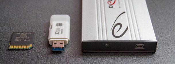


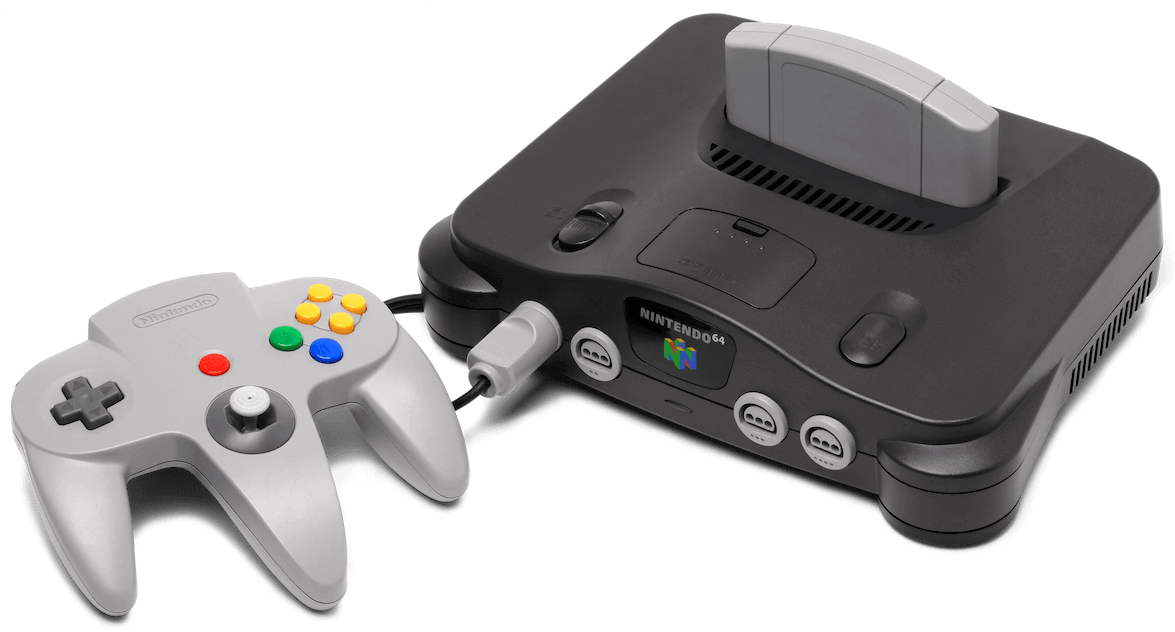
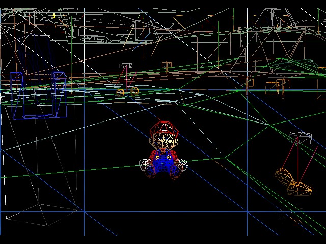
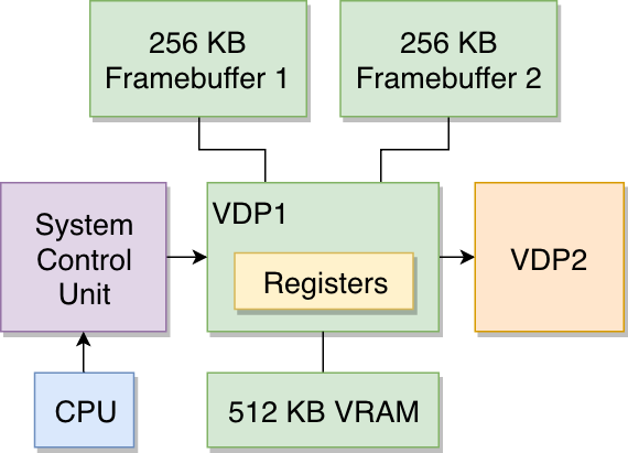
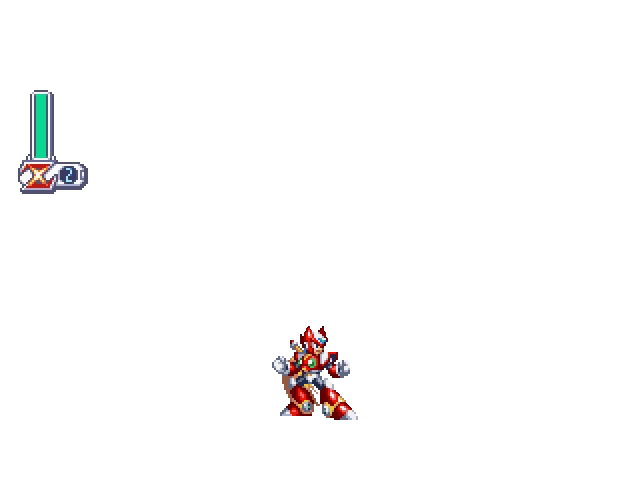
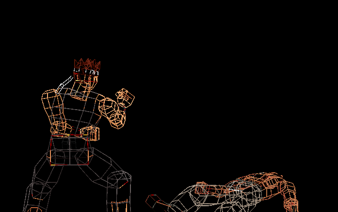
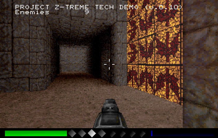
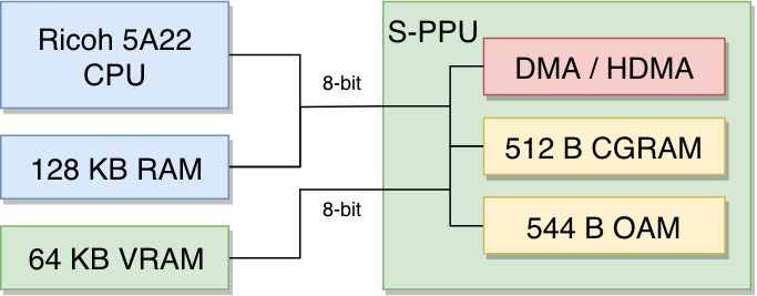
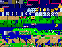
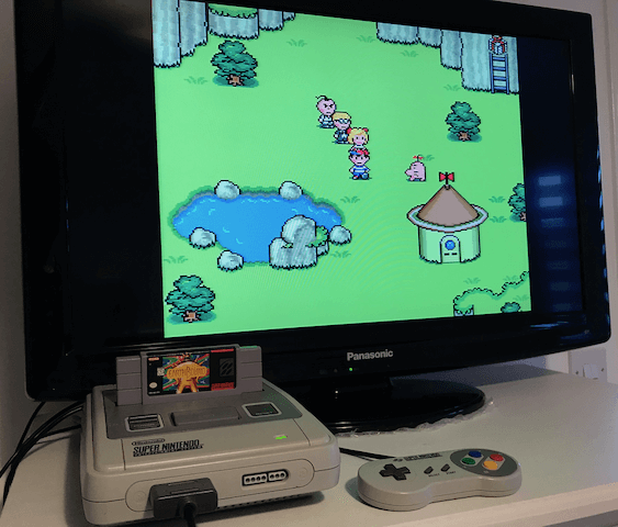
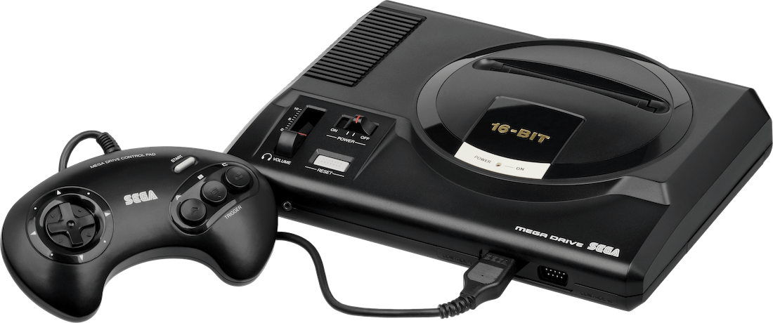
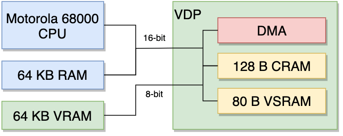
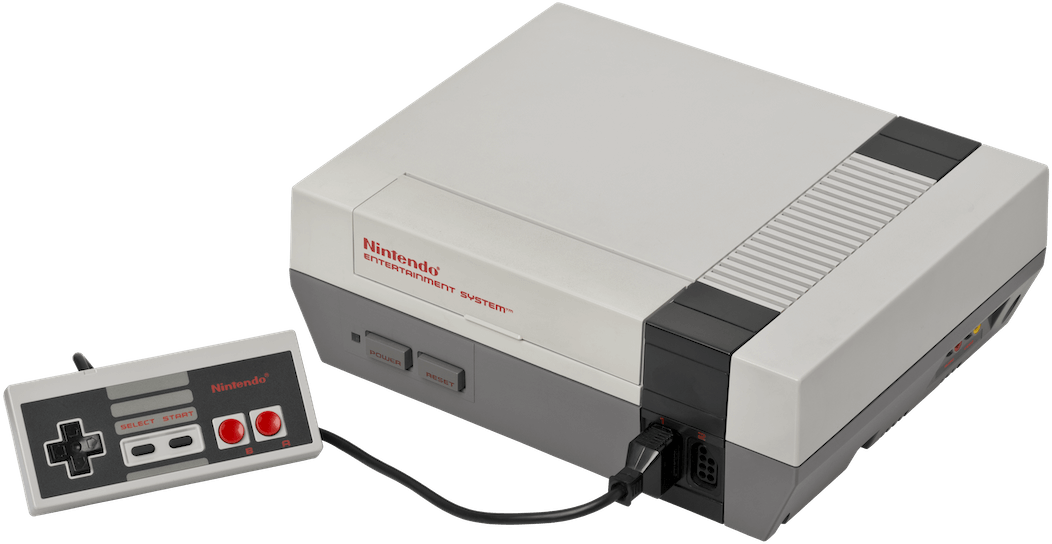
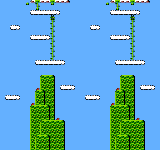
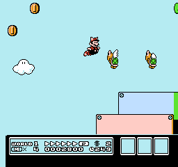
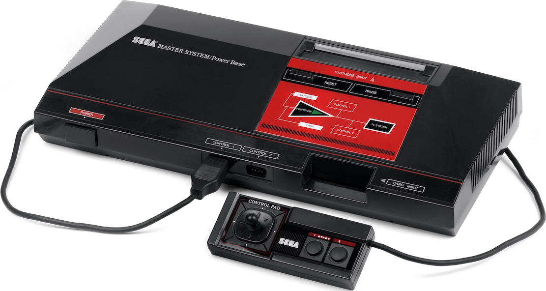
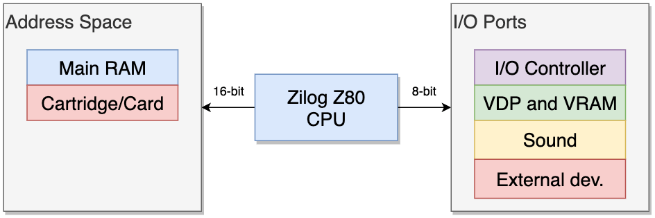